
Specification Sheet


PD-5WS-DV, PD-6ANS
®
SPECIFICATION SUBMITTAL Page
Job Name:
Job Number:
Model Numbers:
Caséta® Wireless In-Wall Switch
369831c 2 10.28/15
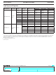
Load Type and Capacity
Model Number Description Voltage Load Type Minimum Load
Maximum Load
4
Not Ganged End of Gang Middle of Gang
PD-5WS-DV-XX
1, 2
Two-wire
switch
120 V~
Incandescent /
Halogen
25 W 600 W 450 W 350 W
277 V~
Incandescent /
Halogen
25 W 1350 W 110 0 W 800 W
120 V~ MLV 25 W 600 VA /475 W 450 VA / 350 W 350 VA / 275 W
277 V~ MLV 25 W 1350 VA /1075 W 1100 VA / 875 W 800 VA / 625 W
120 V~
General
Purpose Fan
0.4 A 3 A 3 A 3 A
120 / 277 V~ LED Use LUT-MLC
3
5 A 4 A 3 A
120 / 277 V~ Fluorescent Use LUT-MLC
3
5 A 4 A 3 A
120 V~ ELV Use LUT-MLC
3
600 W 450 W 350 W
277 V~ ELV Use LUT-MLC
3
1350 W 110 0 W 800 W
PD-6ANS-XX
2, 5
Neutral-wire
switch
120 V~
Incandescent /
Halogen
10 W 720 W 720 W 600 W
MLV 10 W 720 VA 720 VA 600 VA
Fan 0.1 A 3.6 A 3.6 A 3.6 A
LED 1 bulb 6 A 6 A 5 A
Fluorescent 1 ballast 6 A 6 A 5 A
ELV 10 W 720 VA 720 VA 600 VA
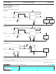
1
No Neutral Required.
2
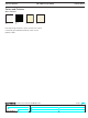
“XX” in the model number represents color/finish code.
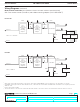
3
To ensure proper operation of the switch with LED, fluorescent, and ELV loads, a LUT-MLC may be required, especially at lower wattages. If the status LED
on the switch is flashing or solid red in color, a LUT-MLC must be installed. To guarantee best performance, installing a LUT-MLC with these load types
regardless of wattage is recommended. Rarely, some load types may still flicker or glow in the off state even with the LUT-MLC installed, in which case a
different load may be required.
4
See “Ganging and Derating” section.
5
Neutral required.
2