
Installation Manual


Wiring Diagrams
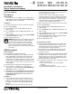
NTR-15 and NTR-20 Receptacle Wiring
Ground (Green or Bare)
Live (Black)
Neutral (White)
125 V~
60 Hz
Switch
(controls upper receptacle)
Ground (Green or Bare)
Live (Black)
Neutral (White)
125 V~
60 Hz
Wiring Notes:
1. Wire terminals accept No. 10, 12 or 14 AWG (6, 2.5 or 1.5 mm
2
) wire.
Solid copper only.
2. See device for proper strip length of wires.
See Note Below
Warning: Mounting means not grounded. Receptacle does not self
ground when mounting it to a wallbox. A ground wire connection
is required for receptacle grounding. Failure to connect a ground
wire to the green grounding screw terminal will result in an
ungrounded receptacle.
NOTE: To control each section of the
receptacle independently, cut off the
connecting link with a wire cutter.
Cutting Brass Screw Terminals
Before
After
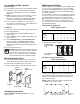
NTR-15-GFCI and NTR-20-GFCI Receptacle Wiring
Ground fault receptacle protecting one outlet only.
Ground fault receptacle protecting part of branch circuit.
Ground (Green or Bare)
Live (Black)
Neutral (White)
125 V~
60 Hz
Line
GFCI Receptacle
P - Protected (shown in gray)
NP - Not Protected
PNPNPNP
Ground (Green or Bare)
Hot (Black)
Neutral (White)
125 V~
60 Hz
Line
Load
GFCI Receptacle
PNPNP P
P - Protected (shown in gray)
NP - Not Protected