
Installation Manual
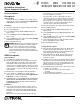


Remove inner side
sections (shaded)
only.
Do not remove outer
side sections.
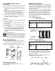
Single-gang
wallbox
3/4 in (19 mm) space (use chase nipple
or Lutron P/N “PLUS-ADPTR-3.5”)
Four-gang
wallbox
Side Sections Removed
Wallbox Requirement Chart
Number of Small Controls
0 1 2 3 4 5 6
0 0 1 2 3 4 5 6
Number 1 1 3 4 5 6 7 8
of Large 2 3 5 6 7 8 9 10
Controls 3 5 7 8 9 10 11 12
4 7 9 10 11 12 13 14
Wallbox Requirement Chart
Number of Small Controls
0 1 2 3 4
0 0 1 1+1 4 4+1
Number 1 1 3 5 6 8
of Large 2 4 6 7 8 10
Controls 3 6 8 10 11 13
4 9 11 12 14 15
Note: When ganging an even number of small controls with side
sections intact, use gangable 3 x 2 in (76 x 51 mm) wallboxes.
Space an additional wallbox 3/4 in (19 mm) apart from the other
wallboxes. A 3/4 in (19 mm) chase nipple is recommended as a
spacer between wallboxes.
Example: Wallbox arrangement required for ganging 4 small
controls with no side sections removed:
No Side Sections Removed
Remove inner side sections from controls. Using pliers, bend side
sections up and down until they break off.
Multigang Installation
Multiple receptacles can be installed in a common gangable wallbox
or a series of interconnected wallboxes for a clean, consolidated
appearance. Lutron multigang faceplates are available to complete
the installation. Refer to instruction sheet supplied with multigang
faceplates for installation.
For new installations, receptacles can be ganged without removing
side sections, but, to reduce the size of the multigang installation or
to fi t existing wallboxes, inner side sections must be removed.
Note: When ganging any combination of small and large controls,
place all small controls on one end of the gang and all large con-
trols on the other. Use the chart below to determine the number of
required gangable wallboxes.
Isolated Ground Receptacle
Important Notes
1. Do not install this receptacle unless you are a qualifi ed electrician.
2. The grounding contact on the isolated ground receptacle is
isolated from the mounting means to reduce electromagnetic
interference.
3. Caution: Care must be given to the specifi cation of a system
with isolated ground receptacles since the grounding
impedance is controlled only by the grounding wires and does
not benefi t functionally from any parallel grounding paths.
4. Connect only No. 12 or 14 AWG (2.5 or 1.5 mm
2
) copper or
copper-clad wire to this device. Do not connect aluminum wire
to this device. See device for strip length.
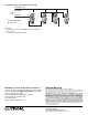
Installation
1. Turn power OFF. Remove old receptacle and disconnect all wires.
2. Refer to Wiring Diagrams.
3. Connect live (black wires) to brass screw terminal(s), and
tighten securely.
4. Connect neutral (white wires) to silver screw terminal(s), and
tighten securely.
5. Connect isolated ground wire to green grounding screw
terminal, and tighten securely. Note: Isolated ground wire
should be insulated and readily distinguishable (as in green
with yellow striped insulation) from the building ground (green
insulation).
6. Refer to Mounting Instructions.
Warning: Mounting means not grounded. Receptacle does
not self ground when mounting it to a wallbox. A ground
wire connection is required for receptacle grounding.
Failure to connect a ground wire to the green grounding
screw terminal will result in an ungrounded receptacle.
Mounting Instructions
1. Push wires into wallbox, allowing room for receptacle to be
inserted. Do not pinch wires between wallbox and receptacle.
2. Mount receptacle to wallbox using screws provided.
3. Replace faceplate adapter (if removed) and snap on faceplate.
Receptacle
Faceplate Adapter
Faceplate
Adapter
Mounting Screws
Receptacle
Mounting Screws
Cleaning Instructions
Clean control with a soft damp cloth only. Do not use any
chemical cleaners.