
Cut Sheet
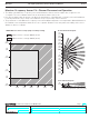
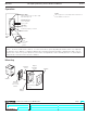
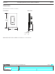
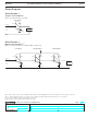
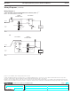
Table Of Contents

®
SPECIFICATION SUBMITTAL Page
Job Name:
Job Number:
Model Numbers:
Maestro® Occupancy/Vacancy Sensor with C•L Dimmer Sensor
369748a 8 01.11.13
Wiring Diagrams (continued)
1
Only one sensor dimmer can be used per multi-location circuit.
2
A single standard mechanical 3-way switch or up to 9 companion dimmers may be connected to a sensor dimmer. Standard mechanical 3-way switch
cannot be combined with companion dimmer. Total blue terminal wire length may be up to 150ft (46m).
3
Diagram 3 shows a typical retrofit scenario, where one mechanical 3-way switch is being replaced with a sensor dimmer. The remaining mechanical 3-way
switch needs to be modified to effectively convert it to a single pole switch. For new construction, a standard mechanical single pole switch can be used here.
3-way Installation with Standard Mechanical Switch (120 V~)
1, 2
MSCL-OP153M and MSCL-VP153M
Brass
Blue
Green
Wire
Ground
Sensor Dimmer
Green screw
Ground
120 V~
60 Hz
Line/Hot
Neutral
Load
Standard
mechanical switch
3
Black
Jumper wire
Different
color screw
(Common)
Wiring Diagram 3
OR
Black
Ground
Sensor Dimmer
Green
Wire
Ground
120 V~
60 Hz
Line/Hot
Neutral
Load
Standard
mechanical switch
3
Blue
Jumper wireDifferent
color screw
(Common)
Green screw
Brass
8