
Cut Sheet
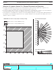
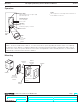
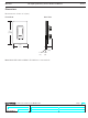
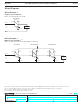
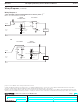
Table Of Contents

®
SPECIFICATION SUBMITTAL Page
Job Name:
Job Number:
Model Numbers:
Maestro® Occupancy/Vacancy Sensor with C•L Dimmer Sensor
369748a 7 01.11.13
Wiring Diagrams
Single Location Installation
1
MSCL-OP153M and MSCL-VP153M
Brass
Black
Blue
1
Ground
Line/Hot
Neutral
120 V~
60 Hz
Load
Wiring Diagram 1
Sensor Dimmer
Multi-Location Installation
2, 3, 4
MSCL-OP153M and MSCL-VP153M with MA-R or MSC-AD
Brass
Black
Blue
Ground
Companion Dimmer
Brass
Black
Blue
Ground
120 V~
60 Hz
Brass
Black
Blue
Ground
Line/Hot
Neutral
Load
Sensor Dimmer Companion Dimmer
Wiring Diagram 2
1
When using controls in single location installations, tighten the blue terminal. Do not connect the blue terminal to any other wiring or to ground.
2
Up to 9 companion dimmers may be connected to a sensor dimmer. Total blue terminal wire length may be up to 150 ft (46 m).
3
Only one sensor dimmer can be used per multi-location circuit.
4
S ensor dimmer can be installed in any location in the circuit.
Green
Wire
Green
Wire
Green
Wire
Green
Wire
7