
Cut Sheet


®
SPECIFICATION SUBMITTAL Page
Job Name:
Job Number:
Model Numbers:
EcoSystem® Five Control Input Digital Dimming Ballasts
369454k 2 05.27.16
Specifications
Regulatory Approvals
• UL
® Listed (evaluated to the requirements of UL935)
• CSA certified (evaluated to the requirements of C22.2
No. 74)
• Select ballasts are NOM Listed (contact Lutron
® for
more information)
• S Mark Certified
• Class P thermally protected
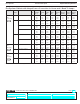
• Some model numbers are not for sale in California.
See tables on Pages 4-7 for details. Also see Lutron
®
Application Note #601, CEC Title 20 Regulation, for
more information.
• Meets ANSI C82.11 High Frequency Ballast Standard
• Meets FCC Part 18 Non-Consumer requirements for
EMI/RFI emissions
• Meets ANSI C62.41 Category A surge protection
standards up to and including 4 kV
• Manufacturing facilities employ ESD reduction
practices that comply with the requirements of ANSI/
ESD S20.20
• Lutron
® Quality Systems registered to ISO9001:2008
• This product may cause interference to radio
equipment and should not be installed near maritime
safety communications equipment or other critical
navigation or communication equipment operating
between 0.45 and 30 MHz.
Performance
• Operating Voltage: 120, 220/240, 277V~ at
50 or 60Hz
• Grounding: ballast and fixture must be grounded for
proper dimming
• Dimming Range: 100% to 10% measured relative light
output
• Lamp Starting: programmed rapid start
• Lamp Current Crest Factor: less than 1.7
• Light Output Variation: Constant ±2% light output for
line voltage variations of ±10%
• Lamp Life: Average lamp life meets or exceeds
specified lamp ratings
• Power Factor: 0.95 minimum
• Total Harmonic Distortion (THD): Less than 10%*
• Maximum Inrush Current: 3 A per ballast at 277 V~,
7 A per ballast at 120 V~
• Class 2 Output: +20 V - 50 mA maximum (one
daylight sensor, one keypad and one occupancy
sensor can be connected)
Environment
• Minimum lamp starting temperature: 50 °F (10 °C)
• Relative humidity: less than 90% non-condensing
• Sound Rating: Class A
• Maximum ballast case temperature: 167 °F (75 °C)
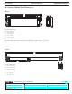
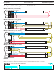
Ballast Wiring & Mounting
• Ballast is grounded by a mounting screw to the fixture
• Terminal blocks on the ballast accept the following
wire gauges:
– Power Wiring, Lamp Wiring, and EcoSystem
®
digital link: only one 16 or 18 AWG (0.75 or 1.5 mm
2
)
solid per terminal
– Class 2 Sensors: only one 22 AWG (0.34mm
2
) solid
per terminal
• Only one wire per terminal
• Class 2 sensor wiring must be separated from all
power and Class 1 wiring, consult all applicable local
and national codes
• Ballast mounts using two screws (or sheet metal
feature and one screw) within a fluorescent fixture
• Wiring from the ballast to lamp sockets should not
exceed 7 ft (2 m) for T8, T5, and T5HO lamps
• Wiring from the ballast to lamps sockets should not
exceed 3 ft (1 m) for T5 Twin Tube lamps
Lamp Seasoning
Refer to lamp manufacturer for lamp seasoning
requirements prior to dimming.
* Models EC5T514JUNV1 and EC5T817JUNV1 have less than 15% THD
2