
Cut Sheet


®
SPECIFICATION SUBMITTAL Page
Job Name:
Job Number:
Model Numbers:
EcoSystem® Five Control Input Digital Dimming Ballasts
369454k 17 05.27.16
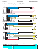
EcoSystem® Ballast Wiring:
Multiple Devices
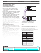
Multiple Sensors with One Ballast
• EcoSystem® ballasts accept wiring for one daylight
sensor input, one occupant sensor input and one IR
input (wallstation or IR receiver).
• EcoSystem
® daylight sensors have IR outputs that
allow the device to operate as a programming port.
In applications where a daylight sensor and
wallstation are wired to the same ballast, do not
connect the white wire of the daylight sensor to
the ballast. The wallstation operates as the
programming port through its integral IR receiver.
• Use the chart below as a guide for wiring multiple
devices to a ballast.
How to Use the Chart
Connect a sensor to a ballast from the “Devices” column (in bold). Along
the selected device row, are “Y’s” and “N’s”. Where a “Y” is placed, the
device at the top of that column can also be connected to the same
ballast. An “N” indicates no connection allowed.
Devices Daylight
Sensor
(with IR)
Occupant
Sensor
Wallstation
or
IR receiver
Daylight
Sensor
(no IR)
Daylight Sensor
(with IR)
YNN
Occupant
Sensor
YYY
Wallstation or
IR Receiver
NY Y
Daylight sensor
(no IR)
NYY
Example: When a Daylight Sensor with IR is connected to a ballast,
then only an occupancy sensor can be added for the system to
properly function.
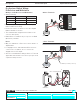
J Case Terminals
+20V
Common
IR
Occ
Daylight
Class 2
(22 AWG Solid)
17