
Cut Sheet


®
SPECIFICATION SUBMITTAL Page
Job Name:
Job Number:
Model Numbers:
EcoSystem® Five Control Input Digital Dimming Ballasts
369454k 14 05.27.16
EcoSystem® Ballast Wiring:
Daylight Sensor
Wiring to a Daylight Sensor
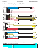
• Sensor wiring summary:
Sensor Wire Ballast Terminal Terminal Color
Red +20 V - Red
Black Common Black
White IR White
Yellow Daylight Yellow
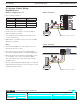
• Make sure that the supply breaker to the Digital
Ballast is OFF when wiring.
• Connect the four conductors to the four Digital
Ballast terminals as shown.
• The maximum wire length from the ballast to the
sensor is 50 ft (15 m).
• Ballast Class 2 terminals only accept one 22 AWG
(0.34 mm
2
) solid wire.
Notes
• Consult the daylight sensor specification sheet to
properly position the sensor.
• Do not place the sensor above pendant fixtures,
directly below lighting fixtures, or within skylight wells.
• When wiring both a wallstation and daylight sensor
to one ballast, only connect the IR wire (white)
from the keypad. Cap off the white wire from the
daylight sensor.
• All sensor and wallstation wiring is Class 2. Follow all
applicable national and local codes for proper circuit
separation and protection.
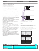
G Case Terminals
J Case Terminals
Daylight Sensor 22 AWG (0.34 mm
2
) solid only
22 AWG (0.34 mm
2
) solid only
Daylight Sensor
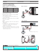
NEU
DH
SH
LINE
+20V
Common
IR
Occ
Daylight
Class 2 (22 AWG Solid)
Class 2
Bus
E1
E2
+20V
Common
IR
Occ
Daylight
Class 2
(22 AWG Solid)
14