
Operating Guide

3. a. Contractor shall provide an appropriate barrier (partition) to
isolate jack from high-voltage wiring when ganged with a
dimmer, fan-speed control, switch, or receptacle. This
complies with NEC Articles 800-3 and 820-13.
b. Telephone jack shall be designed to mate with standard
4- or 6-conductor modular jacks, and be compatible with
2, 4, or 6 conductor lines. Telephone jacks shall meet
FCC Part 68, paragraph F standards to ensure compatibility
with U.S. telephone systems.
c. Cable TV jacks shall be the coaxial type, designed for use
with standard 75-Ohm cables.
C. Wallplates Lutron Satin Colors Style
1. Wallplates shall be manufactured from durable polycarbonate
plastic with satin finish, and shall attach to the basic components
without using exposed hardware or screws.
2. Multigang wallplates shall provide a continuous, seamless cover
for up to six-ganged decorator-style control and accessory
combinations with no exposed hardware or screws.
3. Multigang wallplates shall include an adapter plate for proper
device alignment and wallplate attachment.
4. Control, accessory and wallplate profiles shall not exceed
.30 inches from wall surface to faceplate front surface.
5. Color variation of any satin finish control or wallplate shall not
exceed a change in E of 1, CIE L*a*b* color units.
6. Visible parts of dimmers, switches, standard receptacles,
cable jacks or any wallplate shall exhibit ultraviolet stability when
tested with multiple actinic light sources as defined in ASTM
D4674-89.
2.03 S
OURCE
Q
UALITY
C
ONTROL
A. All dimming controls shall be 100% function tested at the time of
manufacture. Statistical sampling plan shall not be acceptable.
PART 3 – EXECUTION
3.01 I
NSTALLATION
A. Contractor shall furnish all devices (dimmers, accessories, &
wallplate kits), labor and other services necessary for the proper
installation of the devices as indicated on the drawings and specified
herein.
B. Contractor shall be responsible for derating dimmer capacity if side
sections are removed.
C. Contractor shall run separate neutral wires in 120/208 VAC
installations.
D. Devices shall be installed utilizing manufacturer's recommended
application, wiring and installation instructions.
E. Contractor to provide seamless wallplate covers per specification
2.02 for all devices ganged in a common box. Contractor shall
provide barriers within the box where required by code.
3.02 F
IELD
Q
UALITY
C
ONTROL
A. Twenty-four hours a day, seven days a week, global customer
service and technical hotline available.
B. Supplemental information shall be provided by manufacturers
Internet site.
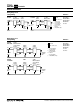
4. Magnetic Low-Voltage (MLV) Transformer Dimmers
a. Provide MLV dimmers for direct control of up to 1000 volt
amps of electronic low-voltage load.
b. Dimmers shall contain circuitry specifically designed to
control and provide a symmetrical AC waveform to the input
of magnetic low-voltage transformers per UL1472 section
5.11.
c. Dimmers shall not cause a magnetic low-voltage
transformer to operate above the transformers rated
operating current or temperature.
d. Dimmer shall be capable of operating in either 3-way switch
location.
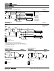
5. Fluorescent Dimming Ballast Dimmers
a. Provide Fluorescent dimmers for direct control of fluorescent
dimming ballasts up to the manufacturers specified rating.
b. Dimmers shall be designed to operate the following ballasts.
Dimmers and ballasts shall be produced by the same
manufacturer to ensure proper ballast/control compatibility:
1) Hi-lume
® Architectural Dimming Ballasts (1% 3-wire)
2) Hi-lume
® CompactTM Lamp Dimming Ballasts
(5% 3-wire)
3) Eco-10
TM Lighting Management Dimming Ballasts
(10% 3-wire)
4) Tu-Wire™ High Performance Dimming Ballasts
(5% 2-wire)
6. Remote dimming modules for high power loads
a. Where lighting loads exceed the full rated capacity of single
dimmers, provide a Diva Satin Colors incandescent dimmer
driving high power modules. High power module and
dimmer shall be from the same manufacturer to ensure
compatibility.
b. High power modules shall be remotely mounted.
c. High power module shall be rated and UL listed for control of
incandescent, magnetic low-voltage, electronic low-voltage,
fluorescent, and neon/cold cathode loads in increments of
2,000 Watts up to 30,000 Watts.
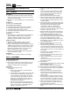
7. Fan-Speed Controls:
a. Fan-speed controls shall be UL Listed, CSA and NOM
approved, Lutron Diva Satin Colors style.
b. Quiet fan-speed model shall provide three speed settings
with paddle providing preset on and off.
c. Quiet fan-speed control shall provide single-pole/3-way
control of one paddle fan (1.5A max.).
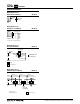
B. Accessories Lutron Satin Colors Style
1. Switch Components Lutron Satin Colors Style
a. Switches shall provide on/off control of any 120/277 VAC
load up to 15A. Switches shall be UL Listed as general-use
AC switches, Lutron Satin Colors style.
b. Switches shall be available in single-pole, 3-way and 4-way
configurations.
2. Receptacle Components Lutron Satin Colors Style
a. All receptacles shall be UL Listed, CSA and NOM approved.
b. Receptacles shall be two pole, three wire ground and rated
for 15A at 125VAC. All receptacles shall be NEMA
configuration type 5-15R.
c. Ground-fault interrupter receptacles shall be Lutron Satin
Colors style with two-pole, three-wire ground and rated 15A
at 125VAC Configuration shall be of the duplex type with
rectangular NEMA WD-6 design. Receptacles shall have a 5
milliampere ground-fault trip level with "test" and "reset"
buttons.
Lutron Electronics Co., Inc.
7200 Suter Road • Coopersburg, PA 18036 U.S.A.
Made and printed in U.S.A. 12/00 P/N 360-393 ©2000
Controls
™