Please Read R Contents Panel Dimensions Mini Panel Standard Panel Large Panel Extra-Large Panel 4 5 6 7 Panel Mounting Panel and TUB Mounting Rough-In Panel Interior Mounting 8 9 11 12 13 Temporary Lighting Activate Loads in Bypass Complete Installation Remove Bypass Jumpers 16 16 17 17 Warranty Contact Information 19 20 Overview Use this guide to successfully install a switching panel. This guide describes panel installation, wiring, and load activation.
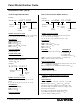
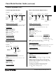
Panel Model Number Guide Softswitch128TM (XPS) Feed-Through Model Numbers Branch Circuit Breaker Model Numbers Example Example X P S 2 4 - 1 2 0 F T- C G P _ _ _ _ XPS24-1204ML-20-CGP____ Number of Circuits in Panel Feed Voltage FeedThrough Type Number of Circuits in Panel Feed Voltage Custom Panel Suffix Feed Voltage1, 2 Omit for dual voltage 120 for 120 V 230 for 230 V (CE) 240 for 220-240 V (non-CE) 277 for 277 V Load Circuit Rating 16 A per circuit Custom Panel Suffix Contact Lutron for option
Panel Model Number Guide (continued) GRAFIK SystemsTM (XP) Feed-Through Model Numbers Branch Circuit Breaker Model Numbers Example Example XP24-120FTML-CGP____ XP24-1204ML-20-CGP____ Number of Circuits in Panel FeedThrough Type Feed Voltage Custom Panel Suffix Number of Circuits in Panel Number of Circuits in Panel Indicates number of switching circuits in the panel: 4, 8, 12, 16, 20, 24, 28, 32, 36, 40, 44, or 48 Load Circuit Rating 16 A per circuit Custom Panel Suffix Contact Lutron for option
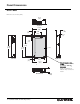
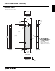
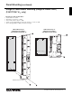
Panel Dimensions Mini Panel Dimensions are in inches (mm). 14.38 (365) Top View 15.875 (403) 2.2 (56) 4.2 (107) 8.00 (203) 0.15 (4) 1.34 (34) 21.50 (546) 24.00 (610) 24.50 (622) Left Side Cover 2.21 (56) 10.75 (273) 15.13 (384) Right Side Note for Rough-In Tub (models XINT4 to XINT16, or SINT8 to SINT16):: Keep clear! Inside of solid black line indicates keep-out area for interior. Front View Bottom View 4 Installation Guide for Switching Panels 4.
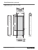
Panel Dimensions (continued) Standard Panel Dimensions are in inches (mm). 14.375 (365) Top View 15.875 (403) 2.43 (62) 4.21 (107) 8.00 (203) 0.15 (4) 2.69 (68) 41.75 (1060) 59.50 (1511) 59.00 (1499) Cover 2.43 (62) Left Side 11.00 (279) 15.125 (394) Note for Rough-In Tub (models XINT20 to XINT48, or SINT20 to SINT48):: Keep clear! Inside of solid black line indicates keep-out area for interior. Right Side Front View Bottom View R 4.
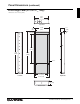
Panel Dimensions (continued) Large Panel (120/277/347 V only) Dimensions are in inches (mm). 22.0 (559) Top View 6.30 (160) 23.50 (597) 2.50 (64) 0.15 (4) 3.34 (85) 45.00 (1143) 63.50 (1613) 63.00 (1600) Cover Left Side 18.50 (470) Right Side 22.75 (578) Front View 6.
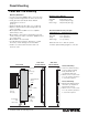
Panel Dimensions (continued) Extra-Large Panel (277/347 V only) Dimensions are in inches (mm). 22.0 (559) Top View 3.0 (76) 6.3 (160) 23.50 (597) 0.15 (4) 3.45 (88) 68.0 (1727) 82.0 (2083) 82.50 (2096) Cover 18.5 (470) Left Side Right Side 22.75 (578) Front View 6.
Panel Mounting Panel and TUB Mounting Mounting Guidelines • For Indoor Use Only! NEMA, Type 1 enclosure, IP20. • Large and extra-large panels for surface mount only. • Panel generates heat. Mount where ambient temperature is 32-104 ºF (0-40 ºC). • Relative humidity must be <90% non-condensing. • Reinforce wall structure for panel weight and local codes; see table. • Mount panel where audible noise is acceptable. (Internal relays click.) • Mount panel so line (mains) voltage wiring is at least 6 feet (1.
Panel Mounting (continued) Rough-In Panel Interior Mounting (Rough-in Panels ONLY) (120/277/347 V only) • • • • • Mounting for SINT or XINT Plate: Insert interior into TUB. Rest interior on bottom of TUB. Press interior flat into back of TUB. Insert 3 screws (provided) as shown into interior to secure to TUB. All mounting guidelines apply (see previous page).
Wiring Feed-Through Panel: Feed and Load Wiring • Use a trough when the switching panel is far away from the distribution panel. Splice neutrals in trough. • Wire the switching panel similar to a lighting distribution panel. Run feed and load wiring. • Use the switching panel to provide temporary lighting by leaving the bypass jumpers in place. (See page 16 for more details.) Typical load circuit Power feed (hot/live) Distribution panel Wire Sizes • Power Feed (Hot/Live): #14-#10 AWG (2.5-4.
Wiring (continued) Panel with Branch Circuit Breakers: Feed and Load Wiring (120/277/347 V only) Wiring Tips • Wire the switching panel similar to wiring a lighting distribution panel: • Run feed and load wiring. No other wiring or assembly required. Bypass jumpers do not remove The switching panel can provide temporary lighting: • Wire all loads. • Leave the bypass jumpers in place. • Use branch circuit breakers at the distribution panel to switch lights on and off.
Wiring (continued) Panel with Isolation Switch: Feed and Load Wiring (230/220-240 V only) Wiring Tips • Wire the switching panel similar to wiring a lighting distribution panel. • Run feed and load wiring. No other wiring or assembly required. Bypass jumpers do not remove Typical switch leg Switched Hot/Live #14-#10 AWG (2.5-4.0 mm2) Load L SL N L SL N L SL N L SL N The switching panel can provide temporary lighting: • Wire all loads. • Leave the bypass jumpers in place.
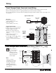
System Wiring Overview Review the options below for information on wiring your panel correctly into your specific system. Common Signal Common Signal { { Softswitch128 Setup and Operation Manual for detailed wiring information. Contact closure input Contact closure input (CCI) 1 (CCI) 2 Common +24 V MUX MUX Drain Sense A. Softswitch128TM (XPS) panel: Refer to the 1 2 3 4 D 5 Controller Terminals B.
Ratings Softswitch128TM (XPS) Use the charts below to determine feed and load wiring sizes for Softswitch128 panels. Note that load circuit wiring sizes are shown bottom right.
Ratings (continued) GRAFIK SystemsTM (XP) Use the charts below to determine feed and load wiring sizes for GRAFIK Systems panels. Note that load circuit wiring sizes are shown bottom right.
Temporary Lighting You do not need to install a temporary distribution panel. Connect load wires into the appropriate terminal blocks. Each input breaker can supply power to a load while the bypass jumper protects the module from load faults. H SH Input circuit breaker Warning! Verify that the panel is fed from the correct voltage. A feed miswire or loss of a feed neutral can cause over-voltage damage to the equipment. Do NOT remove bypass jumpers at this point--they protect the modules from load faults.
Complete Installation You have completed your panel installation. For Onsite Factory Commissioning, call Lutron Technical Support and select Startup to schedule a field service visit. Allow for 10 working days between day of call and scheduled visit. If you purchased Telephone Startup (Softswitch128/XPS only), stop here and complete the Control Location, Panel, and Control Station Tables that are located in the back of the Setup and Operation Manual.
Notes 18 Installation Guide for Switching Panels R
Warranty Lutron Electronics Co., Inc. One Year Limited Warranty For a period of one year from the date of purchase, and subject to the exclusions and restrictions described below, Lutron warrants each new unit to be free from manufacturing defects. Lutron will, at its option, either repair the defective unit or issue a credit equal to the purchase price of the defective unit to the Customer against the purchase price of comparable replacement part purchased from Lutron.
Contact Information Internet: www.lutron.com E-mail: product@lutron.com WORLD HEADQUARTERS USA Lutron Electronics Co., Inc. 7200 Suter Road, Coopersburg, PA 18036-1299 TEL +1.610.282.3800 FAX +1.610.282.1243 Toll-Free 1.888.LUTRON1 Technical Support 1.800.523.9466 Brazil Lutron BZ do Brasil Ltda. AV, Brasil, 239, Jardim America Sao Paulo-SP, CEP: 01431-000, Brazil TEL +55.11.3885.5152 FAX +55.11.3887.7138 North and South America Technical Hotlines USA, Canada, Caribbean: 1.800.523.9466 Mexico: +1.888.235.