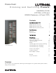
Please Read R Español Installation Guide LCP128TM (LCP) and GRAFIK SystemsTM (LP and CCP) English Dimming and Switching Panels Contents Panel Dimensions Mini Panel Standard Panel 6 7 Panel Mounting 8 16 17 17 Warranty Contact Information 19 20 Nederlands Activate Loads in Bypass Complete Installation Remove Bypass Jumpers Português 9 10 10 11 12 14 15 Chinese Wiring/Ratings System Wiring Overview Feed and Load Wiring Overview Temporary Lighting Ratings Feed-Through Panel: Feed and Load Wi
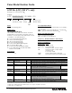
Panel Model Number Guide LCP128TM (LCP) (120 V only) See page 5 for 230/220-240 V Example L C P - 2 X 2 D 1 A 4 T- 1 2 0 4 M L - 2 0 Prefix Modules: Quantity and Type Feed Voltage Feed Type Branch Circuit Breaker Rating Prefix LCP = LCP dimming panel Module Types _X _S _D _Q _A _M _F _T List modules in the order shown above. Insert the quantity before each module code. Omit codes for modules not used in panel. See table below for limits on numbers of modules per panel.
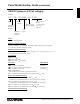
Panel Model Number Guide (continued) GRAFIK SystemsTM (LP) (all voltages) Example LP7/28-1204ML-20-CGP____ Prefix Feed Voltage Branch Circuit Breaker Rating Number of Dimming Modules Number of Dimming Circuits Custom Panel Suffix (contact Lutron for custom options) Feed Type Prefix LP = LP dimming panel Number of Dimming Modules Indicates number of 4-circuit (4U) dimming modules in the panel: 1 through 8; also indicates number of full load circuits Number of Dimming Circuits Indicates number of dimmi
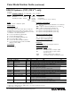
Panel Model Number Guide (continued) GRAFIK SystemsTM (CCP) (120 V only) Example C C P - 2 X 2 L 1 A 4 T- 1 2 0 4 M L - 2 0 - C G P _ _ _ Prefix Modules: Quantity and Type Feed Voltage Feed Type Branch Circuit Breaker Rating Prefix CCP = Custom combination panel Module Types _X _L _A _M _F _T List modules in the order shown above. Insert the quantity before each module code. Omit codes for modules not used in panel. See table below for limits on numbers of modules per panel.
Panel Model Number Guide (continued) GRAFIK SystemsTM (CCP/LCP) (230/220-240 V only) Example C C P - 1 X 4 L 2 T- 2 3 0 4 I S - C E - L C P - C G P _ _ _ Prefix Modules: Feed Quantity and Voltage Feed Type Type Region Suffix Controller Type Prefix CCP = Custom combination panel Module Types _X _L _E _A _M _T List modules in the order shown above. Insert the quantity before each module code. Omit codes for modules not used in panel. See table below for limits on numbers of modules per panel.
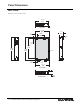
Panel Dimensions Mini Panel Dimensions are in inches (mm). 14.375 (365) Top View 15.875 (403) 2.2 (56) 4.21 (107) 8.00 (203) 0.15 (4) 1.34 (34) 21.50 (546) 24.00 (610) 24.50 (622) Left Side Cover 10.75 (273) 2.21 (56) Right Side 15.13 (384) Front View Bottom View 6 Installation Guide for Dimming and Switching Panels 4.
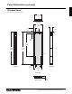
Panel Dimensions (continued) Standard Panel Dimensions are in inches (mm). 14.375 (365) Top View 15.875 (403) 2.43 (62) 4.21 (107) 8.00 (203) 0.15 (4) 2.69 (68) 41.75 (1060) 59.50 (1511) 59.00 (1499) Cover 2.43 (62) Left Side 11.00 (279) Right Side 15.125 (394) Front View Bottom View R 4.
Panel Mounting Mounting Guidelines • For Indoor Use Only! NEMA, Type 1 enclosure, IP20. • Panel generates heat. Mount only where ambient temperature is 32-104 °F (0-40 °C). • Relative humidity must be < 90% non-condensing. • Reinforce wall structure for panel weight and local codes; see table. • Allow 12 in. (305 mm) clearance above and below panel. • Mount within 7° of true vertical. • Mount panel where audible noise is acceptable. (Internal relays click.
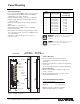
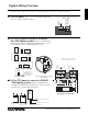
System Wiring Overview Review the options below for information on wiring your panel correctly into your specific system. A. LCP128 panel: Refer to the LCP128 Setup and Operation Manual for detailed wiring information. Contact closure input Contact closure input (CCI) 1 (CCI) 2 Common Signal Common Signal Common +24 V MUX MUX Drain Sense { { 1 2 3 4 D 5 Controller Terminals B.
Wiring (continued) Feed and Load Wiring Overview Feed Wiring (Mains Voltage Wiring) • Preferred feed wiring entry for panels with main lugs/isolation switch is from the bottom left of the panel. • Preferred feed wiring entry for feed-through panels is from the top or bottom left of the panel, wired directly to module terminal blocks. • Run wiring so that line (mains) voltage wiring will be at least 6 ft. (1.83 m) from sound or electronic equipment and its wiring.
Ratings LP/LCP/CCP Panels Feed-Through Panels (all voltages) Number of Modules 1 2 3 4 5 6 7 8 9 Feed Type Max. Feed 1Ø, 2W 120 V : 20 A 230 V : 13 A or 16 A 220-240 V : 16 A #14-#10 AWG (1.5-4.0 mm2) Panels with Breaker (120 V only) Panels with Main Lugs (120 V only) Number of Modules Feed Type Number of Modules 1 2 3 1Ø, 2W 1Ø, 3W 3Ø, 4W #14-#10 AWG (1.5-4.
Feed-Through Panel: Feed and Load Wiring (all voltages) General Notes • Typical dimming/switching legs shown. • Do not remove bypass jumpers until after load wiring has been verified. Wire sizes for power feed, to each input • Power feed: #14 AWG (2.5 mm2) to #10 AWG (4.0 mm2) • Neutral feed: #14 AWG (2.5 mm2) to #10 AWG (4.0 mm2) Wire sizes for load wiring, from each output • Dimmed hot (live): #14 AWG (2.5 mm2) to #10 AWG (4.0 mm2) • Load neutral: #14 AWG (2.5 mm2) to #10 AWG (4.
Feed-Through Panel: Feed and Load Wiring (continued) 4-Circuit Motor Module (4M) Raise R L R Lower L R Circuit breaker L Connecting an NGRX-FDBI to a Panel R Hot/Live L Bypass jumper Dimmed DH Feed hot/live DH Hot/Live Neutral Hot/ DH Live H Load N Feed N Neutral N N DH N Lutron Neutral Lutron Eco-10 or FDBI Hi-lume Circuit FDB ballast breaker H Feed N N N N N Neutral 2-Circuit Dimming Module (2U) (LCP and CCP only) Refer to FDBI Installation Sheet for detailed wiring.
Panel with Main Lugs: Feed Wiring Dimming and Switching Panels (120 V only) Notes • See page 15 for load wiring details. • On dimming panels only, the input breaker of Circuit 1 supplies current to Load Circuit 1 and to the Control Wiring (2 A draw max.). Panels with switching modules have a dedicated circuit breaker for the control circuit.
Panel with Main Lugs: Load Wiring Typical Dimming/Switching Leg Shown Caution! Do not remove bypass jumpers until after load wiring has been verified.
Activate Loads in Bypass Activate Loads in Bypass Load circuit wiring A. Complete load wiring. B. Check that the bypass jumpers are in place. These jumpers protect from load faults and must be used to check load wiring when it is installed or modified. Caution! Verify that the panel is fed from the correct voltage. A feed miswire or loss of a feed neutral can cause damage to the equipment. C. Turn circuit breaker 1 ON.
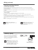
Complete Installation You have completed your panel installation. For Onsite Factory Commissioning, call Lutron Technical Support and select Startup to schedule a field service visit. Allow for 10 working days between day of call and scheduled visit. If you purchased Telephone Startup (LCP128 only), stop here and complete the Control Location, Panel, and Control Station Tables that are located in the back of the Setup and Operation.
Notes 18 Installation Guide for Dimming and Switching Panels R
Warranty R Installation Guide for Dimming and Switching Panels Chinese Lutron Electronics Co., Inc. One Year Limited Warranty For a period of one year from the date of purchase, and subject to the exclusions and restrictions described below, Lutron warrants each new unit to be free from manufacturing defects.
Contact Information Internet: www.lutron.com E-mail: product@lutron.com WORLD HEADQUARTERS USA Lutron Electronics Co., Inc. 7200 Suter Road, Coopersburg, PA 18036-1299 TEL +1.610.282.3800 FAX +1.610.282.1243 Toll-Free 1.888.LUTRON1 Technical Support 1.800.523.9466 Brazil Lutron BZ do Brasil Ltda. AV, Brasil, 239, Jardim America Sao Paulo-SP, CEP: 01431-000, Brazil TEL +55.11.3885.5152 FAX +55.11.3887.7138 North and South America Technical Hotlines USA, Canada, Caribbean: 1.800.523.9466 Mexico: +1.888.235.