Sivoia QED™ Wireless Roller 64™ for HomeWorks® Installation Instructions
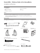
Sivoia QED TM | Wireless Roller 64 for HomeWorks Installation Instructions Tools Required: Tape Measure Wire Cutter/Stripper Pliers #2 Phillips Screwdriver 1/4” Hex-Head Driver Level Power Drill Notes: 1) 2) For Wireless Roller 64 programming refer to the HomeWorks® Illumination Online Help. The Electronic Drive Unit (EDU) will need to be powered to complete installation. Wireless Shades will not function until they are addressed and programmed using the HomeWorks® Illumination Software.
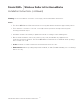
Sivoia QED TM | Wireless Roller 64 for HomeWorks Installation Instructions (continued) Warning: Incorrect installation can lead to severe injury, follow all installation instructions. Notes: • The Sivoia QED Wireless Roller 64 must be used only with window treatments approved by Lutron. • There must be a clearance of at least 1.3 feet (0.4 meters) between the fully lowered system and any permanent object. • Installation shall be executed by a qualified electrician according to national wiring rules.
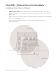
Sivoia QED TM | Wireless Roller 64 for HomeWorks Installation Instructions (continued) • RF Device Placement: Wireless shades must be located within 30 feet (9m) of an RF Signal Repeater or an RF Processor. The distance between repeater and processor must be less than 60 feet (18m). Wireless shades will not function until they are addressed and programmed. See the HomeWorks Illumination Software Online Help.
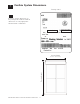
1 1 Confirm System Dimensions Package Label 1.1 Compare system dimensions on the package label with the window dimensions to verify appropriate window/shade combination.
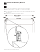
2 Position the Mounting Brackets 2.1 Mark the location of the mounting brackets so that they are centered over the window. Note: Bracket to Bracket distance = Fabric Width + 1.5” (38 mm) = System Width. Note: For ceiling and jamb mount, allow clearance to prevent fabric from rubbing against trim, window, top treatment, etc. Note: Wall mount may require blocks (not provided) to clear trim.
3 Install the Mounting Brackets 3.1 Install the first mounting bracket. 3.2 Install the second mounting bracket. Note: Put a screw in the center of each slot. Use slots as needed to ensure brackets are level and plumb as positioned.
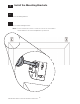
4 Pre-drill for Cable Run DANGER - Locate and lock breaker to the shade power supply in the OFF position or unplug the power plug-in transformer before doing any wiring. 4.1 Wall Mount Choose one of the options below to drill for cable access. Note: Cable should exit from wall, ceiling, or jamb on EDU side of system. Note: Leave 12-18” (30-45 cm) of cable exposed. Wall Mount with wires through: A) Wall: 1” in from end of system and .5” from top of bracket B) Ceiling: .5” in from end of system and .
4 4.2 Pre-drill for Cable Run: (continued) Ceiling Mount Ceiling Mount with wires through: A) Wall: 1” in from end of system and .5” from ceiling B) Ceiling: 1” in from end of system and .5” from back of bracket C) Jamb: 1” from back of bracket and .
4 4.3 Pre-drill for Cable Run: (continued) Jamb Mount Jamb Mount with wires through: A) Wall: .5” from ceiling and .5” from outside of jamb B) Ceiling: .5” from wall and .5” from outside of jamb C) Jamb: .5” from ceiling and .
5 Wire 3-Pin Terminal Block 5.1 Strip 2” of jacket off cable run from the wall. 5.2 Wire 3-Pin terminal block (provided) to cable using the included screwdriver.
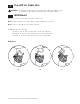
6 Orient the Buttons and Wiring 6.1 For the following bracket and button orientations, route the wires as shown.
7 Mount the Shade 7.1 Install the idler side of the shade onto its bracket. 7.2 Depress the spring loaded idler by pressing the shade towards the idler, and install the EDU side of the shade onto its bracket.
8 Adjust the Shade 8.1 Ensure that the shade is level and centered. 8.2 Adjust shade by removing the necessary screws and moving the brackets as needed, or installing bracket leveling spacers. Note: You may have to remove the shade to access the bracket screws. 8.3 Reinstall and tighten the screws.
9 Secure the Antenna 9.1 For optimal performance secure the antenna in 1 of 3 configurations shown below using the antenna clips provided. WARNING: - The antenna is covered with a clean Plastic sleeve to protect it. Do not cut the antenna or remove the plastic sleeve. Do not modify the antenna. Antenna mounted parrallel with shade use these configurations. When Pocket or Fascia is not used. Antenna mounted straight down.
10 Connect Terminal Blocks 10.1 Plug 7-pin terminal block on cable into EDU terminal block attached to shade bracket (a cable tie can be used to secure the terminal blocks together). 10.2 Dress wires to ensure fabric does not rub while the shade is moving. WARNING: Do not cut wires coming out of shade. Doing so will damage the antenna. 10.3 Copy the serial number located on every shade’s harness and shade location on page 21 of this manual.
11 Secure and Check the Shade 11.1 Tighten retaining screws in each bracket to secure the shade.
11.2 Secure and Check the Shade (continued) Reconnect power to the shade power supply. Use the programming stylus to run the shade up and down using the adjustment buttons ( ), re-level if needed. Observe: Pay careful attention to the shade roll up to ensure that it does not telescope extremely to one side or the other. Tip: Slight telescoping is normal.
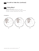
12 Setting Limits from the EDU Setting the Open Limit from the EDU Note: Setting the Open Limit lower than the Close Limit will cause the shade to move down when raise is pressed and up when lower is pressed. 12.1 Tap the “Open Limit Button” ( ), the green LED on the roller shade EDU will turn on steady, indicating that the EDU is in “Set Open Limit Mode.” 12.2 Adjust the position of the EDU to the desired Open Limit using the adjustment buttons ( ). 12.
12 Setting Limits from the EDU (continued) Setting the Close Limit from the EDU 12.4 Tap the “Close Limit Button” ( ). The green LED on the roller Shade EDU will turn on steady, indicating that the EDU is in “Set Close Limit Mode”. 12.5 Adjust the position of the EDU to the desired Close Limit using the adjustment buttons ( ). 12.6 Press and hold the “Close Limit Button” ( ) for 5 seconds.
13 Finish System Programming The Sivoia QED shade is now installed, wired, and the OPEN/CLOSE limits for each shade have been set. The next step is to finish programming the system, using the HomeWorks Illumination Software.
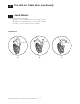
14 Troubleshooting Symptom Shade will not move using adjustment buttons on EDU... Solution ...EDU is not powered - check EDU Power. By unplugging and re-plugging in EDU. LED should light for 5 seconds. ...Shade is caught on something - free shade. ...Shade is not programmed to keypad or event. Shade does not fully open or fully close... ...Limits have been set incorrectly - refer to “set open limit” and “set close limit” sections on re-set limits using HW1 Software. ...
Location Shade Serial Number Shade 1 33 2 34 3 35 4 36 5 37 6 38 7 39 8 40 9 41 10 42 11 43 12 44 13 45 14 46 15 47 16 48 17 49 18 50 19 51 20 52 21 53 22 54 23 55 24 56 25 57 26 58 27 59 28 60 29 61 30 62 31 63 32 64 SIVOIA QED Wireless Roller 64 Installation Instructions 22 TM Location Serial Number
Technical Assistance WORLD HEADQUARTERS CUSTOMER SERVICE /E-MAIL Lutron Electronics Co., Inc. 7200 Suter Road Coopersburg, PA 18036 United States Tel: +1-610-282-3800 Fax:+1-610-282-1243 shadinginfo@lutron.com CUSTOMER SERVICE/ORDERING INTERNET: TECHNICAL SUPPORT & SERVICES USA +1-800-523-9466 – 24 hours/7 days www.lutron.com USA +1-888-LUTRON1 08.00 - 20.00 EST Limited Warranty Lutron offers an 8-year limited warranty for our shading systems.