
User's Manual

R
Job Name:
Job Number:
Model Numbers:
Page
SPECIFICATION SUBMITTAL
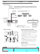
Wiring Diagram
1 2 3 4 5 6 7
RJ45 jack:
Ethernet link
(to PC or A/V
equipment)
Ethernet
link/
activity
Ethernet speed
On = 100 Mbit/sec
Off = 10 Mbit/sec
CAT5 Cable:
maximum 328 ft.
(100 m)
To PC or AV equipment. For Ethernet link, use CAT5 cable provided to connect to
auxiliary equipment. The Ethernet link LED will light continuously when link is present
and will flash when there is link activity. Additional Ethernet network equipment and
cables provided by others.
PELV (Class 2: USA) Power in
500 mA 12 - 24 V
(powered by 120 V transformer, included).
RS232 Cable:
maximum 50 ft.
(15 m)
COM
TxD
RxD
To PC or AV equipment: Use the 9-pin cable
provided, or follow the chart below.
RS232 Pin Connect Wiring
Typical PC or Pin on
RS232 Interface A/V equipment 9-pin cable
Common Com 5
Receive TxD 3
Transmit RxD 2
LED 1: Power
LED 2: Ethernet link
LED 3: Unused
LED 4: RS232 link TX
LED 5: RS232 link RX
LED 6: Unused
LED 7: Unused
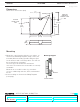
System Communication Notes
• Stanza lighting controls, keypads, and interfaces
must be located within 20 feet (6 m) of a Stanza
device configured as a repeater. Multiple devices
configured as repeaters may be necessary to
provide adequate coverage.
• A total of 3 devices maximum can be configured
as repeaters.
• Devices configured as repeaters must be within
20 feet (6 m) of another device configured as a
repeater.
• Stanza lighting controls cannot be controlled
wirelessly and Stanza keypads will not function
until they are addressed and programmed.
System Limits
• 31 devices maximum
• 20 feet (6 m) from device to repeater devices
• Dimmers, keypads, or contact closure devices
can be repeaters
System Overview
20 ft. (6 m) max.
from repeater device
Dimmer
Keypad
20 ft. (6 m) max.
from repeater device
20 ft. (6 m)
maximum
sz-ci-prg-4 06.06.08
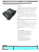
Wireless Control InterfacesSZ-CI-PRG
StanzaTM
Diagnostic
LEDs
4