
User's Manual


7
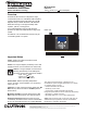
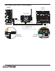
Processor Board Connections
1. RS-232 Port (Link 3 and 7): Standard 9-Pin male con-
nectors for connecting to a computer for programming, to
a modem for remote programming, or to an external con-
trol system (A/V system, HVAC, etc.).
2. Ethernet Jack (Link 9): Standard 8-Pin RJ-45 jack for
connecting the processor to an Ethernet Hub/Switch, to a
laptop computer for remote programming, or to an
external control system (A/V system, HVAC, etc.).
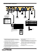
3. Inter-Processor Link (Link 2): Allows up to 16 proces-
sors (both RF and Wired) to be connected together.
4. Contact Closure Inputs: connection for 3 dry contact
closures plus common.
5. Hybrid Repeater Link (Link 8): Allows connection of
Hybrid Repeaters.
6. Configuration DIP Switches: All DIP switches should be
placed in the OFF (left) position for normal operation. The
HomeWorks
® Utility will prompt the programmer if any
subsequent changes to the DIP switches are required.
7. Power Input Jack: Input jack for the 15 VDC adapter.
Center pin is positive.
8. Initialize Button: Used to reset the processor.
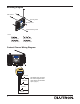
Ethernet Port (Link 9)
RS-232 Ports
(Links 3 and 7)
Inter-Processor
Link (Link 2)
Hybrid Repeater
Link (Link 8)
Power Input Jack
Contact
Closure Inputs
Configuration DIP Switches
Initialize
Button
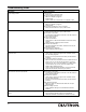
PIN
1
2
3
4
5
6
7
8
9
Name Description
DCD Data Carrier Detect
TXD Transmit Data
RXD Receive Data
DSR Data Set Ready
GND Ground
DTR Data Terminal Ready
CTS Clear To Send
RTS Request To Send
RI Ring Indicate
DIP Switch
1
2
3
4
5
6
OFF ON
Normal Mode Boot Mode
User-Configured 9600 Baud
Baud Rate
Normal Mode Not Used
Normal Mode Not Used
Normal Mode Not Used
Normal Mode Not Used
Pin Processor
1 Transmit +ve
2 Transmit -ve
3 Receive +ve
4 No Connection
5 No Connection
6 Receive -ve
7 No Connection
8 No Connection
Ethernet Hub/Switch
Receive +ve
Receive -ve
Transmit +ve
No Connection
No Connection
Transmit -ve
No Connection
No Connection
1
2
3
4 NC
5 NC
6
7 NC
8 NC
1
2
3
4
5
6
7
8
NC
NC
NC
NC
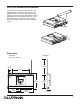
Crossover Cable Configuration
A crossover cable is used when
connecting the processor to a laptop or
other non-hub device (a/v systems,
HVAC, etc.)
1
2
3
4
5
6
7
8
OFF - Left
ON - Right
Example: Setting Switch #6 ON.