
User's Manual


3
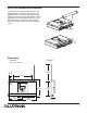
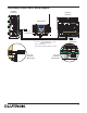
Port Cover Removal and Installation
The Port Cover can be removed for access to the
Initialize Button, Configuration DIP Switches, and
Diagnostic LEDs. The cover is removed by gently
pulling up on the front edge to disengage the snaps.
Replace the cover by inserting the two tabs on the
back of the cover into the slots on the processor.
Gently press down on the front edge to engage the
snaps.
Slots
Tab
Tab
Press
Down
11.54"
(293mm)
8"
(203mm)
1.25" (32mm)
6.16"
(157mm)
6.7"
(170mm)
0.70"
(18mm)
Front View
(Port Cover attached)
Side View
5.77"
(147mm)
1.77"
(45mm)
Dimensions
7"
(178mm)