
User's Manual


If the RF Processor is connected to a modem, a null
modem adapter is needed between the processor and the
attached modem.
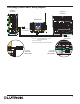
7. Connect Ethernet Link (if applicable). Connect a
standard RJ45 connector to the Link 9 Ethernet jack on
the processor for system programming or communications
with other equipment. A crossover cable is required for a
direct connection to a computer. If plugging in to a
network, a standard cable is used (see Processor Board
Connections, page 7). The orange LED (ACT) will
illuminate when there are any Ethernet signals being
transmitted or received on Link 9. The green LED (CON)
will illuminate when the Link 9 is connected to a
hub/switch/router or a computer.
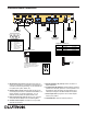
8. Connect Hybrid Repeater Link (if applicable). For
Hybrid Repeaters that control wireless devices, connect
the communication wires to Link 8 as configured in the
HomeWorks Illumination
TM Software. Important: Use only
the blue terminal block connector that is provided with the
RF Processor.
9. Connect external input closures (if applicable). The
processor accepts three low-voltage dry contact closures.
Important: Use only the blue terminal block connector
that is provided with the RF Processor.
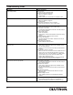
When using the input closures: Verify compatibility of
external devices. The input closures are intended for use
with devices that provide dry contact closures. The inputs
may be used with ground-referenced, solid-state closures
if the closures have an on-state saturation voltage of less
than 2 V and an off-state leakage of less than 50 µA.
Dry contact or solid-state closures must be capable of
switching 15 V at 10 mA. The closures must stay in the
closed or open states for at least 40 msec in order to be
recognized by the processor. If there is any question as to
whether the contact closure device is compatible with
these specifications, contact the manufacturer of that
device.
The Contact Closure Input Status LEDs will illuminate
when a contact closure is closed on the corresponding
input.
2
Installation
1. Find a suitable location for the RF Processor. Place
the RF Processor in a convenient and accessible
location. See RF Coverage Diagrams on page 8 and 9.
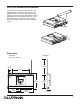
2. Mount the RF Processor. Mount RF Processor to wall
using the appropriate mounting hardware provided (see
Mounting Diagram). Orient the processor’s antenna for
optimal performance. For most installations, the antenna
should be oriented vertically.
Note: DO NOT ground the RF Processor. DO
NOT mount the RF Processor in a metal
enclosure.
3. Connect Inter-processor Link (if applicable). The inter-
processor link is used for communication between
multiple HomeWorks
® processors. Connect control wiring
to the Inter-Processor link (4-position terminal block), if
required. Do not connect the +15V terminal (terminal 2).
If this processor is to be the first or last processor in the
daisy chain, attach one of the LT-1 link terminators
provided across the MUX and MUX (terminals 3 and 4).
(See Low-Voltage (Class 2/PELV) Wiring Diagram, page
5). If LT-1s are unavailable, a 1/2 W resistor between 100
and 150 Ohms may be placed across terminals 3 and 4
to provide termination. Important: Use only the blue
terminal block connector that is provided with the RF
Processor.
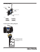
4. Apply power to the RF Processor.
The RF Processor has battery-backed memory and
timeclock devices. The battery provides power to these
devices during power outages and other temporary power
interruptions. In vacation homes and other residences
which are not continuously occupied, the RF processor
MUST be powered by a circuit that is never turned off
even when the residence is unoccupied.
5. Address the RF Processor. Use the RF Processor
display to set address.
6. Connect Serial Link (if applicable). Connect a standard
DB9 male connector to the Link 3 or 7 RS-232 connector
on the RF Processor for system programming or
communications with other equipment. A cable with all 9
pins straight through (not a null modem) is required for
programming the system via the serial link using a laptop.
Verify LED lights
when powered
Plug in power
cord and
adapter
Use wallplate
screw to attach
adapter to outlet
(if applicable)