
User's Manual


4
RadioTouch Tabletop Transmitter Addendum
Hardware Installation
RadioTouch
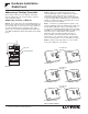
Setting the ON light level of a two
button, dimmable lighting column -
Remote Method
Note: No DIP switches need to be switched to perform
this operation.
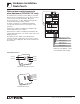
Step A - Press and hold the ON and the lower buttons
for 5 seconds. The lights will flash to notify you that you
are in Preset Adjust Mode, and settle at 100% light
level.
Step B - Using the raise/lower buttons in that column
on the transmitter controlling the Controller that you are
adjusting, set the lights at the new ON level.
Step C - Press and hold the ON and raise buttons for 5
seconds. The lights will flash to notify you that the ON
level has changed.
Step D - Press and hold the ON and the lower buttons
for 5 seconds to exit Preset Adjust Mode. The lights will
flash and return to their maximum light level. Test the
ON button to make sure the light level is correct. If not,
repeat steps A through D.
Notes:
• The Controller will not react to preset button presses
from any transmitter while the Controller is in Preset
Adjust Mode.
• Preset light levels may be affected by a photosensor
input. As ambient light increases / decreases the
preset light levels will scale accordingly.
Press and hold
these two buttons
for 5 seconds
Step A & D Step C
Press and hold
these two buttons
for 5 seconds
Press and hold
these two buttons
for 5 seconds
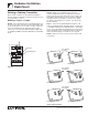
Setting the ON light level of a two
button, dimmable lighting column -
DIP Switch Method
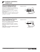
Step A - Flip DIP switch #1 down on the Controller.
After the switch is flipped the Controller will be in Preset
Adjust Mode. (If a photosensor is connected to this
Controller your lights may change level when DIP
switch #1 is flipped.)
Step B - Using the raise/lower buttons on the
transmitter controlling the Controller that you are adjust-
ing, set the lights at the new ON level.
Step C - Press and hold the ON and raise buttons for 5
seconds. The lights will flash to notify you that the ON
level has changed.
Step D - Flip DIP switch #1 back up to exit Preset
Adjust Mode.
Notes:
• The Controller will not react to preset button presses
from the transmitter while the Controller DIP switch
#1 is flipped to the down position.
• Preset light levels may be affected by a photosensor
input. As ambient light increases / decreases the
preset light levels will scale accordingly.
Step A & D Step C
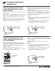
1234 5678 9101112 13141516
CLASS 2 LOW VOLTAGE WIRING
12345
Power
Status Program
Burn-In
123
Sivoia Cntrl 1
Sivoia Cntrl 2
RTA-RX-F-SC
Radio Frequency Controller
LISTED 243C
Ind. Cont. Eq.
Coopersburg, PA 18036
STATUS INDICATOR OPERATION
ON - Burn-in Mode
Slow Blink -Normal Operation Mode
Fast Blink - Program Mode
Very Fast Blink - Receiving RF Data
RadioTouch
12
345678910
11
12 13 14
15 16
Occ. Com
Signal
15V
24V
Circuit Com
Sw Closure 1
Sw Closure 2
Sw Closure 3
Sw Closure 4
Sw Closure 5
Closure Com
0-10 Purple
0-10 Gray
Receiver
Settings
Terminal connections
are Class 2.
TM
Occ. Sensor
0-10 V
Shade Swi tch C losures
12345
Powered
When Lit
Status
Indicator
Program
Button
Burn-in
Button
RECEIVER SWITCH SETTINGS
1. UP-Preset Lock DN.-Preset Adj.
2. UP-Occ. Sensor DN.-Emerg. Set.
3. UP-FDB Mode DN.-ECO Mode
4. UP-OFF DN.-Min. Light
5. UP-Auto ON DN.-Manual ON
See Installers Guide for System
Addressing and Programming Instructions
®
123
Shade
Settings
SHADE SWITCH SETTINGS
1. UP-A/C Shades DN.-Normal Oper.
PS Signal
© 2000-2002 Lutron Electronics Co., Inc.
Flip DIP switch
#1 to the down
position