
User's Manual


3
RadioTouch Tabletop Transmitter Addendum
Hardware Installation
RadioTouch
Deleting a Tabletop Transmitter
Each column of buttons on the tabletop transmitter
must be deleted separately from the Controller that you
no longer wish to control.
Deleting Columns of Lights
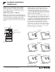
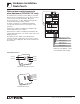
Step A - Press and release the programming button on
the Controller. After the button is pressed the lights will
cycle up and down for 3 seconds to notify you that you
are in programming mode, and settle at 50% light
output. If you are using an RTA-RX-SW the lights will
cycle OFF and ON. The Status LED will be in fast blink
mode.
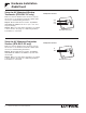
Step B - While in programming mode press the
corresponding buttons in the column that you want to
delete from the Controller and hold for 5 seconds (see
Transmitter diagrams below). The Controller will flash
the lights when the transmitter is deleted. If no lights
are being controlled by the Controller, you will not get
visual feedback.
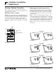
Step C - Press the programming button again to exit
from programming mode. The lights will go to high end
or turn ON, and the Status LED will return to slow blink
mode. To test the Tabletop Transmitter press any button
on the transmitter in the column that has been deleted
and verify that the lights or shades do not respond.
Step D - Repeat for each row you need to delete from
a Controller.
1234 5678 9101112 13141516
CLASS 2 LOW VOLTAGE WIRING
12345
Power
Status Program
Burn-In
123
Sivoia Cntrl 1
Sivoia Cntrl 2
RTA-RX-F-SC
Radio Frequency Controller
LISTED 243C
Ind. Cont. Eq.
Coopersburg, PA 18036
STATUS INDICATOR OPERATION
ON - Burn-in Mode
Slow Blink -Normal Operation Mode
Fast Blink - Program Mode
Very Fast Blink - Receiving RF Data
RadioTouch
12
345678910
11
12 13 14
15 16
Occ. Com
Signal
15V
24V
Circuit Com
Sw Closure 1
Sw Closure 2
Sw Closure 3
Sw Closure 4
Sw Closure 5
Closure Com
0-10 Purple
0-10 Gray
Receiver
Settings
Terminal connections
are Class 2.
TM
Occ. Sensor
0-10 V
Shade Switch Closures
12345
Powered
When Lit
Status
Indicator
Program
Button
Burn-in
Button
RECEIVER SWITCH SETTINGS
1. UP-Preset Lock DN.-Preset Adj.
2. UP-Occ. Sensor DN.-Emerg. Set.
3. UP-FDB Mode DN.-ECO Mode
4. UP-OFF DN.-Min. Light
5. UP-Auto ON DN.-Manual ON
See Installers Guide for System
Addressing and Programming Instructions
®
123
Shade
Settings
SHADE SWITCH SETTINGS
1. UP-A/C Shades DN.-Normal Oper.
PS Signal
© 2000-2002 Lutron Electronics Co., Inc.
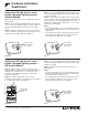
Press and hold
this button
Programming button
Status LED
Step A & C
Press and hold
these buttons
Press and hold
these buttons
Step B - Columns of buttons
Two button Switch Closure Three button Switch Closure
Dimmable Lights Non-dim Lights
Four button Switch Closure Five button Switch Closure