
User's Manual

Installation
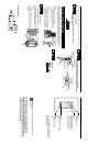
Installing a Wall-Mounted Master Control in a newly installed wallbox.
Check off Steps as completed.
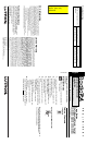
Step 1 Turn power off at circuit breaker panel or remove
fuse from fusebox.
Wiring Diagram
Step 3 Attach wallplate adapter. Mount and align control.
Snap on Claro
® or Satin ColorsTM wallplate (purchased
separately).
Step 4 Turn power ON.
Align Control.
Snap on wallplate.
Operation of the Master Control
Button
Turns lights on/off.
LEDs
Glow when associated
Room or Scene lights are
on. Glow dimly as night
light when lights are off.
Raise
Brighten ROOM or SCENE
lights*.
Lower
Dim ROOM or SCENE
lights*.
* To select the ROOM or SCENE button
you wish to Raise or Lower, quickly tap
that button twice.
Important Wiring Information
Twist wire connec-
tor tight.
Be sure no bare
wire is exposed.
When making wire connections, follow the recommended strip lengths and com-
binations for the supplied wire connectors. Note: Wire connectors provided are
suitable for copper wire only. For aluminum wire, consult an electrician.
Small
Large
Small:
Strip insulation 3/8" for 14 AWG wire
Strip insulation 1/2” for 16 or 18 AWG wire
Use to join one 14 AWG supply wire with one
16 or 18 AWG control wire.
Large:
Strip insulation 1/2" for 10, 12 or 14 AWG wire
Strip insulation 5/8" for 16 or 18 AWG wire
Use to join one or two 12 or 14 AWG supply
wires with one 10, 12, 14, 16, or 18 AWG
control wire.
Step 2 Wire the Control.
Using the wire connectors provided:
• Connect the black control wire to the
HOT wire coming from the breaker
panel.
• Connect the white control wire to the
NEUTRAL wire coming from the break-
er panel.
Black
White
Hot
Neutral
Tighten screws
until snug.
NOTE: Master Controls will not operate until they have been
programmed.
For detailed instructions on programming your Master
Control, refer to the Setup and Installation Guide for a
RadioRA® ChronosTM System Bridge and Timeclock that is
included with a Chronos or the RadioRA Setup Guide that is
included with an RF Signal Repeater.