
User's Manual

4
PRELIMINARY—NOT FOR RELEASE
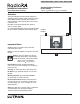
Operation
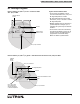
Home Key
Menu
Navigation
Keys
Display Power
LED
Power In LED
Keyboard Port
Reset Button
RS-232 Link
Activity LEDs
1. Home Key: Returns the user to the Home Screen.
2. Menu Navigation Keys: Used to navigate the various
menus and screens for the processor.
3. RS-232 Link Activity LEDs: The LEDs will illuminate
when there are any RS-232 signals being transmitted
(TX LED) or received (RX LED) on that link.
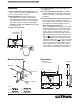
4. RS-232 Port: Standard 9-Pin male connector for con-
necting to an external control system (A/V system,
HVAC, etc.).
5. Contact Closure Inputs: Used for control by external
systems, such as A/V, Security, etc..
6. Reset Button: Used to reset the SBT.
7. Keyboard Port: Allows a computer keyboard to be con-
nected to the SBT for ease of programming and naviga-
tion. Standard PS/2 keyboard connector.
LCD Display
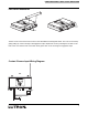
8. RF Activity LEDs: The LEDs will illuminate when there
are any RF signals being transmitted (TX LED) or
received (RX LED).
9. Power Input Jack: Input jack for the 18 V adapter.
Center pin is positive.
10. Power In LED: This LED illuminates when power from
the adapter is present at the Power Input Jack.
11. LCD Display: Displays programming and diagnostic
information. The LCD Display will shut off after 60 min-
utes of inactivity. To restore the display, simply press
any key.
12. Display Power LED: This LED will illuminate when the
LCD Display has power.
3
1
2
RS-232 Port
4
Contact
Closure Inputs
5
6
7
10
11
12
Power Input
Jack
9
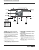
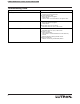
PIN
1
2
3
4
5
6
7
8
9
Name Description
DCD Data Carrier Detect
TXD Transmit Data
RXD Receive Data
DSR Data Set Ready
GND Ground
DTR Data Terminal Ready
CTS Clear To Send
RTS Request To Send
RI Ring Indicate
RF Activity
LEDs
8