
User's Manual

®
SPECIFICATION SUBMITTAL
MODEL NUMBERS:JOB NAME:
JOB NUMBER:
Page
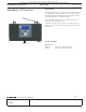
PROCESSORSHomeWorks InteractiveTM RF Processor
048-020 4a 11.05.02
PRELIMINARY
12 3
4
123
4
88
123
4
123
4
123
4
123
4
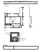
Link 7
RS-232 Link
G1 V1 G2 V2 G3 V3 G4 V4 G5 V5 G6 V6
1234
1234
1234
BUS
6
RXTX
BUS
5
RXTX
BUS
4
RXTX
BUS
3
RXTX
BUS
2
RXTX
BUS
1
RXTX
PROCESSOR
LINK
RXTX
PROCESSOR
LINK
#
OK
*
#
OK
*
3
4
123
4
123
4
3
4
3
4
123
4
3
4
#
OK
*
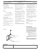
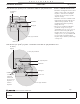
POWER SUPPLY CONNECTION
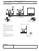
INTER-PROCESSOR WIRING
WIRING
Processor wiring must be in a daisy-chain
configuration. The total length of wire on
the Inter-Processor Link may be up to
1,000 ft. (305m). For wire runs exceeding
50 ft. (15m) in length, LT-1 Link
Terminators must be used on the proces-
sors at both ends of the wire run. Up to 16
Processors (RF or Wired) may be connected
together.
WIRE TYPE
Two pair [one pair #18 AWG (1.0mm
2
),
one pair #22-18 AWG (0.5-1.0mm
2
) twisted
shielded] Class 2/PELV. Lutron wire, model
# GRX-CBL-346S-500, may be used.
LT-1 Link
Terminator
LT-1 Link
Terminator
Wiring Detail
LT-1 Link
Terminator
LT-1 Link
Terminator
Wiring Detail
RF Processor
RF Processor
Wired
Processor
Pin 1 - 1 No. 18 AWG (1.0mm
2
)
Pins 3 & 4 - 1 pair No. 22-18 AWG (0.5 - 1.0mm
2
)
twisted/shielded for data
Pin 2 is not connected