
Installation Guide
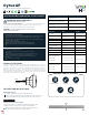

To open the sensor case,
use a pin and press inside
the two small holes on
both sides of the sensor
case and pull upward.
Insert the external wire through the
hole above the case. Then connect the
external wires with the Sensor -
Line (Black) and Neutral (White).
Push and fix the case back.
Note
3
1&2
4
2
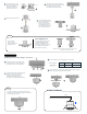
Position the sensor mounting base to
fix and take out the mains wire through
the hole given at the mounting base.
Mount the base on the selected position using screws
Insert the external wire through the hole
above the case. Then connect the
external wires with the Sensor-
Line (Black) and Neutral (White).
Termination will happen within the case.
Connect the sensor unit case with the Mount base (that is already
fixed in step 2) by rotating the case clockwise.
To remove the sensor unit case from the mount
base, apply pressure towards ceiling and rotate the
sensor case anti-clockwise.
SURFACE MOUNT
Mounting sensor on hard ceilings or on surfaces
1
2
3
3
Press and hold the spring
clips (on both sides of the
device) and insert the
sensor into the mounting
hole. Release the spring
clips so that the sensor will
fit in and remain intact.
5
4
2
4
WIRING DIAGRAM
Head: CSK Slotted
Length
38mm 8.3mm 3.7mm
Head Diameter Screw Diameter
Line
Neutral
L
N
To remove the
sensor from the
ceiling, hold and pull
the sensor down
The High bay and Low bay lens
can be interchanged as per
requirement. Rotate the lens
clockwise to connect to the case
and rotate anti-clockwise to
dismantle from the case
Note
Interchanging Lens
Rotate the lens anti-clockwise to remove from the case and
clockwise to connect to the case
Pull upward
3
4
5
Anti-clockwise
Anti-clockwise Anti-clockwise
Clockwise