
Installation Guide
1/2”
Top
Drill this hole for
the power cord.
Hole centers for
mounting screws
(see instructions for
sizing).
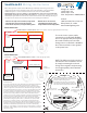
When predrilling mounting screw holes use an
appropriately sized bit for the composition and
thickness of the mounting surface.
Most applications will require a drill bit sized
larger than the minimum diameter of the screw,
but smaller than the maximum thread diameter.
0.190
"
0.140
"
Mounting Screw Minimum Diameters
Size Drill Bit Appropriately
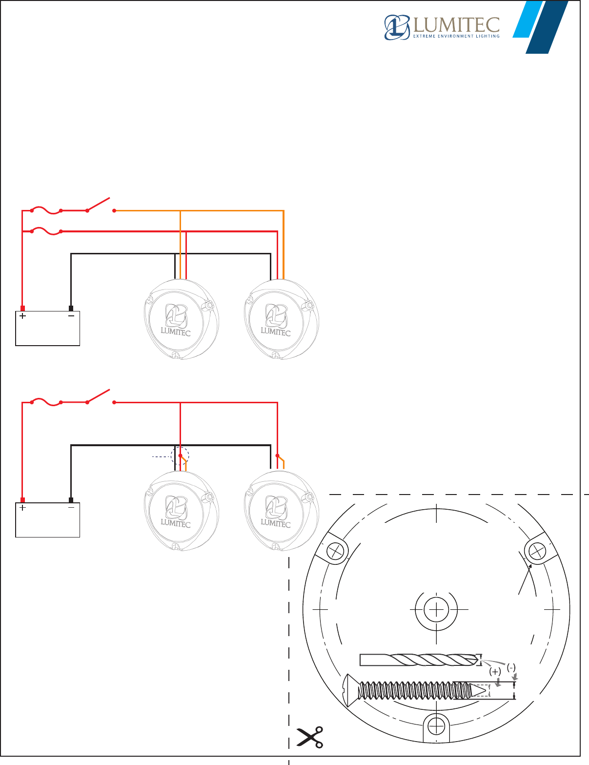
BATTERY
10-30vDC
Orange - Switch Line
Red - Power Line
Black - Negative Line
6A per light
X # of lights
(@ 12vDC)
Fuse/Breaker
Switch
3-WIRE CONNECTION
BATTERY
10-30vDC
Fuse/Breaker
6A per light
X # of lights
(@ 12vDC)
Switch
Orange
- Switch Line
TOGGLE SWITCH or DIGITAL SWITCH - Max current draw 0.1 Amps per light (allows PLI functionality)
HIGH CURRENT SWITCH or RELAY - 6 Amps per light (@ 12vDC)
2-WIRE CONNECTION
SPLICE Power (Red)
& Swtich (Orange)
Wires Together
Red - Power Line
Black - Negative Line
Limited Warranty
The product is warranted to be free from defects in workmanship and materials
for a period of one year from the date of original purchase. Lumitec is not
responsible for product failure caused by abuse, neglect, improper installation,
or failure in applications other than those for which it was designed, intended,
and marketed. Note that some surface corrosion is expected when bare metals
are used in a marine environment. Corrosion of any metal will be especially
aggressive if installation is improper, if bonding is improper or if stray currents
are active in the vicinity of the boat. Lumitec shall not be liable for defects
related to such corrosion. Should your Lumitec product prove defective during
the warranty period, promptly notify Lumitec, and return product, freight
prepaid. Lumitec will, at its option, repair or replace the product or defective
portion without charge for parts or labor, or, at Lumitec, Inc.'s option, refund
purchase price. Products repaired or replaced under this warranty shall be
warranted for the unexpired portion of the warranty applying to the original
product(s). No warranty or armation of fact, express or implied, other than as
set forth in the limited warranty statement above is made or authorized by
Lumitec, Inc. Any liability for consequential and incidental damages is expressly
disclaimed. Lumitec liability in all events is limited to, and shall not exceed, the
purchase price paid.
Voltage: 10 - 30vDC
12vDC Amps: 5A
24vDC Amps: 2.5A
Color Temperature: 6500K (White)
Lumitec
1405 Poinsettia Drive, Suite 10
Delray Beach, FL 33444
www.lumiteclighting.com
• Allows for more lights to be controlled by a single switch
• Switch placement can be much further from lights
• Fewer channels required on your digital switching system
• Will allow for PLI color control via
compatible digital switching system
through a Multi Functional Display (MFD)
SeaBl azeX2 Wiring Instructions
Due to the high lumen output of the SeaBlazeX2 light, suciently rated wiring and electrical
components must be used to minimize voltage drop to the lights. When connecting multiple
SeaBlazeX2 lights to a common switch this becomes even more critical. THE TYPICAL
RECOMMENDATION IS TO SELECT WIRING SYSTEM COMPONENTS TO ENSURE THAT VOLTAGE DROP
FROM POWER SOURCE TO THE LIGHTS DOES NOT EXCEED 3%. To simplify the installation on vessels
with multiple lights Lumitec has introduced a remote switch internal to the SBX2 light, allowing for
less expensive low current wire and components to be used during the installation.
NOTE: The SBX2 can also be wired in a
standard two wire installation as well
by simply connecting the red and
orange wires together and powering
via an appropriately rated switched
power buss.
To use the 3-wire system, simply
connect the red and black 10-30VDC
lines to an appropriately fused power
buss with constant power and the
Orange wire to a switched +10-30VDC
buss referenced to the same ground
as the power lines.
CONNECTIONS MUST
BE DURABLE AND
WATERPROOF