
Installation Guide

Mounting and Operation
Determine where your Seablaze Mini light(s) will be mounted. Mounting surfaces should be at and free
of any existing hardware or holes. Check for interference with the trim/tilt of engines, turning of
rudders, operation of trim tabs, etc. Ideal mounting locations include transoms, the side and back
surfaces of engine brackets, and the undersides of dive platforms. Seablaze Mini lights are not
recommended for mounting on running surfaces (e.g., the bottom surface of a hull). For maximum
performance Seablaze Mini lights should be mounted 6” to 12” (15cm - 30cm) below the waterline.
Mounting at depths greater than 30” (75cm) below the waterline is not recommended. Drill holes as
indicated and mount using fasteners provided. All holes must be thoroughly sealed and light(s) should
be bedded with a quality polyurethane marine sealant.
As with any on-board electrical device, Seablaze Mini lights should only be connected to a circuit which
is appropriately protected by a fuse or circuit breaker. Seek the advice of a qualied marine electrician if
necessary.
Lights may be mounted above or below water. In applications where lights are run out of water for
prolonged periods of time the SeaBlaze Mini’s Active Thermal Management system may temporarily
reduce the power of the light (reduce brightness) to ensure long life. This will in no way damage the
light or permanently reduce light output.
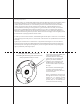
Thoroughly coat the entire back surface
surrounding the mounting stem and screw holes
with polyurethane marine sealant.
Lights may be painted, but ONLY with
paints explicitly intended for
aluminum substrates. Anti-fouling
paints which do not explicitly state
that they are safe for aluminum
substrates can be damaging to the
BayBlaze light, and should not be
used on surfaces within 1” (2.5cm) of
the light.
Once installed, Seablaze Mini lights
should be routinely inspected to
ensure that all connections, fasteners,
and seals are intact.
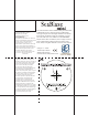
Drill a ¼” (6.5mm) wire clearance hole
through the transom for routing wires
followed by a ½” diameter (13mm)
clearance hole approximately ¼”
(6.5mm) deep to accommodate the
stem on the back of the housing.