
Installation Guide
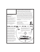
Table Of Contents

Note:
• ORIENTATION IS VERY IMPORTANT! Lights should be mounted with the logo in an
upright position so that the widebeam pattern fans out to illuminate the water surface.
• Lights must be operated on an appropriately fused or circuit breaker protected circuit.
• Lights are not recommended for mounting on running surfaces (e.g., the bottom surface of a hull)
• For best performance, lights should be mounted below the waterline
• Bottom paint is not required, however lights can be painted with any bronze-safe paint if desired.
• Light circuits should be protected with an appropriately sized fuse.
Mounting Location:
Mounting surfaces should be at, clean, dry, and free of any existing hardware or holes. Before mounting ensure that the
light will not interfere with the operation of engines, trim tabs, rudders, etc. Ideal mounting locations include transoms, the
side and back surfaces of engine brackets, and the undersides of dive platforms. For maximum performance SeaBlaze lights
should be mounted 6” to 16” below the waterline. Installation at depths greater than 36” is not recommended.
Mounting your SeaBlaze light:
Tape the mounting template in the desired mounting location. Drill holes for the mounting screws and wire boss as
indicated on the mounting template.
NOTE! The mounting screws provided with your SeaBlaze light, while very corrosion resistant, are softer than typical steel
screws. Extreme care must be taken when driving screws to prevent screw heads from shearing o. The diameter of the
pilot hole required for the mounting screws will depend largely on the composition and thickness of the mounting surface.
• Size pilot holes so that only moderate torque is needed to drive the screw into the mounting surface. Typically this hole
size will be slightly smaller than the outside diameter of the widest threads. Test the size of the mounting hole prior to
installation. Carefully turn screws to avoid breaking them. If screw is too tight, back out and re-size screw hole. When
drilling berglass, slightly countersinking the hole using a 3-uke countersink bit will reduce gelcoat chipping.
• Thoroughly coat the back surface of the SeaBlazeX light with a marine-grade sealant designed for below-waterline
applications. Dab additional sealant on the holes in the mounting surface, forcing some sealant into the holes. Extreme
care should be taken to properly seal the through-hull (wire) hole to prevent water intrusion.
• Press the SeaBlaze rmly into place to bed it in the sealant. Tighten the mounting screws evenly. Sealant should be forced
from all sides as the light is tightened down. Thread the wire strain relief from inside the boat along the power wire. Press if
rmly into the wirehole to properly seal and prevent water intrusion. Allow the sealant to cure thoroughly per the manufac-
turer’s instructions prior to returning the vessel to the water.
Note: Any time a hole is bored into a vessel’s hull (for example mounting screws for transducers, dive platforms,
through-hull ttings, etc.), the possibility of water intrusion into the hull or completely into the vessel exists. Water intrusion
may result in signicant structural damage to a vessel or the vessel sinking. Considerable care should be taken to ensure
that the through-hull hole is thoroughly sealed on both sides of the hull. Additionally, the back (inside) surface where the
wire exits the through-hull hole should be carefully sealed using the wire strain relief.
Operation:
An abrupt OFF/ON toggle of your standard (SPST) switch allows SeaBlazeX to transition through various light output modes.
Under Voltage Diagnostic Mode
If the voltage at the device is less than 10V when the device is on, the device will gradually dim to minimum brightness.
Factors which may result in under voltage conditions include insucient wire gauge, bad battery cell, bad connection at
switch, connectors, fuse and/or circuit breaker. Lumitec, Inc. assumes no responsibility whatsoever for any damage, loss, or
injury that may result from the incorrect installation of this product, including but not limited to the vessel sinking,
structural damage due to water intrusion, electrical malfunction, etc.
Single Color Light Output Modes:
1 – Constant, 2 – Fade, 3 – Flashing/strobe
Dual Color Light Output Modes
1 – Cross-Color Fade – gently undulating color mix, 2 – On, White 3 – On, Blue,
SeaBlazeX Only: 4 – On, White and Blue, 5 – Flashing, two color
4 – On, White and Blue
5 – Flashing, two color
Installation Instructions
SPECTRUM Light Output Modes (ALL MODELS)
Light will cycle through all available colors within the rst 20 seconds, (including white). A brief OFF/ON toggle will allow
the user to select any discrete color during the cycle. After 20 seconds without interruption, the light will continue a full
color cycle over a period of 3 minutes - Discrete colors can still be chosen during the 3 minute cycle. If a discrete color is
not selected, the light will repeat the 3 minute cycle continuously. Light resets after power is o for more than 3 seconds.