
Phau Ntawv Qhia

5|Page
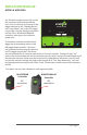
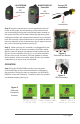
Step 2) Plugthesolenoidvalveintotheapplicableelectrical
outlet.Atthisstage,thefunconalityofthesolenoidvalve
canbetestedbypressingthesolenoidtestbuonlocatedon
theupperleofthecircuitboard.Manuallydepressing(and
holding)thisbuonwillcompletetheelectricalcircuitandwill
openthenormallyclosedsolenoidvalve.Youshouldbeableto
heartheacvaonofthesolenoidvalveatthisstagetoensure
thevalveisfunconingproperly(seeFig.4).
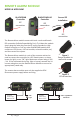
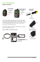
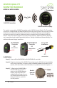
Step 3) MakesureyourUVcontrollerisunpluggedfromthe
powersource.Oncealltheseconneconshavebeenmade,
axthemaleIEPplugofthesolenoidmodulecableintothe
IEPportonthecontroller(seeFig.5),oranyotheravailable
IEPportsuchastheUVsensor,4-20mAmoduleorremote
alarmmodule.ItdoesnotmaerwhichIEPportanymodule
isaachedto,aslongastheyareaached.
OPERATION
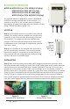
Step 1) PlugtheBLACKCOMBcontrollerintothepower
sourceandmakesurethesolenoidmoduleisacvatedon
thecontroller.Duringthestart-upsequence,theSOLENOID
MODULEscreenwillindicatea“inialized”whenthemodule
isacvatedproperly(seeFig.6).
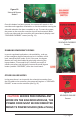
Figure 4
SolenoidTestBuon
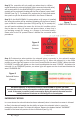
Figure 6
Solenoid
Acvaon
Screens
Sensor IEP
Installaon
IEP
connecon
BLACKCOMB
Controller
BLACKCOMB-HO
Controller
IEP
connecon
IEP
connecon
Figure 5
IEPconnecon
IEP