BLACKCOMB OWNER’S MANUAL EQUIPMENT MODULES Operation & Installation Instructions illuminating technologies for life
Table of Contents Emulator Module .............................................. 1 Remote Alarm Module ...................................... 2 4-20 mA Module................................................ 3 Solonoid Module ............................................... 4 SHERPA Water Quality Monitor Module ........... 8 UV Concierge Module .....................................
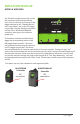
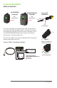
EMULATOR MODULE MODEL # MOD-EMU The Emulator module comes with a male IEP connection (Infinite Expandability Port). Prior to start-up, first ensure all the toggle switches for the “Module Alarms” and “Lamp Alarm” are in the OFF (toggle up) position. Plug the Emulator connector into the IEP on the BLACKCOMB/HO controller, then plug in the controller power cord.
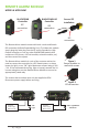
REMOTE ALARM MODULE MODEL # MOD-RAM BLACKCOMB Controller BLACKCOMB-HO Controller IEP connection IEP connection Sensor IEP Installation IEP connection The Remote Alarm module comes with both a male and female IEP connection (Infinite Expandability Port). To initiate the module simply plug the male plug into the IEP on the Standard or High Output controller, or into any other BLACKCOMB module that contains an IEP (sensor, 4-20 mA module, solenoid module, etc.) and then restart the system.
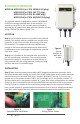
4-20 mA MODULE MODEL # MOD-420 BLACKCOMB Controller BLACKCOMB-HO Controller IEP connection IEP connection Sensor IEP Installation IEP connection The 4-20 mA module comes with both a male and female IEP connection (Infinite Expandability Port). To initiate the module simply plug the male plug into the IEP on the controller, or into any other BLACKCOMB module that contains an IEP (sensor, remote alarm, solenoid module, etc.) The 4-20 mA module must only be supplied at SELV.
SOLENOID MODULE MODEL # MOD-SOL1 (in 110V, NEMA 5-15 plug) MOD-SOL2 (in 230V, CEE 7/7 plug) MOD-SOL3 (in 230V, BS 1363 plug) MOD-SOL4 (in 230V, AS/NZS 3112 plug) The Solenoid Module is designed to connect a NORMALLY CLOSED line voltage solenoid valve to the controller. It is possible to use a 12V or 24V normally closed solenoid by replacing the AC power cord. Note that the maximum contact rating is 240VAC (50-60Hz) / 30VDC / 2A.
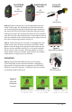
BLACKCOMB Controller BLACKCOMB-HO Controller IEP connection IEP connection Sensor IEP Installation IEP connection Step 2) Plug the solenoid valve into the applicable electrical outlet. At this stage, the functionality of the solenoid valve can be tested by pressing the solenoid test button located on the upper left of the circuit board. Manually depressing (and holding) this button will complete the electrical circuit and will open the normally closed solenoid valve.
Step 2) The controller will only notify you when there is a failure mode whereby the solenoid module (and connected solenoid valve) will be activated. On the BLACKCOMB 5.1 system, the solenoid module will be activated (shutting off the flow of water) upon LAMP FAILURE (see Fig. 7). To remedy this, replace the UV lamp and restart the system as per the directions outlined in the Owner’s Manual. Step 3) On the BLACKCOMB 6.
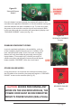
Figure 10 Solenoid Bypass Button Once this button has been pressed, the system will remain in this override mode regardless of whether or not the condition causing the solenoid activation has been remedied or not. To reset the system, the power to the controller must be shut off and restarted. While in this override mode the controller will intermittently display a red “SOLENOID OVERRIDE” screen (see Fig. 11).
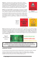
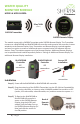
WATER QUALITY MONITOR MODULE MODEL # MOD-SHERPA 50m/164ft (Note 2) SHERPA Transmitter SHERPA Remote Display The module comes with a SHERPA Transmitter and a SHERPA Remote Display. The Transmitter connects to a BLACKCOMB and BLACKCOMB-HO controller and transmits the controller’s status wirelessly to the Remote Display. Every Transmitter and Remote Display is paired together and uses encryption to create a reliable and secure communication link between the two devices.
Operation SHERPA Remote Display Status LED’s Comm. LED Good (Green) Caution (Yellow) Alarm (Red) OFF Flashing ON Power Switch I O Water is safe for consumption. No Active Alarms. Water may not be safe for consumption. Active Minor Alarm, check system for details. Water is NOT safe for consumption. Active Major Alarm, check system for details. Communication is working. Communication is NOT working. Remote Display is Out-of-Range2, Transmitter is disconnected OR controller is powered off.
UV CONCIERGE MODULE MODEL # MOD-APP The UV Concierge module connects to your wireless network (WiFi) and transmits your UV system’s status to the uvconcierge.com webpage. You can then view your status online from anywhere you have internet access, and receive email or SMS notifications of your system’s status on your mobile device.
If you do not currently have a uvconcierge.com account: From the UV Concierge app, click “Add device to account”. This method will automatically populate your module key for you. OR Make note of the Module Key from the label on your UV Concierge module. Go to uvconcierge.com and click the “Register a new device” link. You will need the module key to successfully register your module. If you currently have a uvconcierge.
12|Page
13|Page
illuminating technologies for life 80 Southgate Drive, Unit 4 Guelph, Ontario, Canada N1G 4P5 P: 519-837-3800 TF: 855-837-3801 F: 519-837-3808 info@luminoruv.com www.luminoruv.