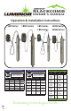
BLACKCOMB OWNER’S MANUAL Operation & Installation Instructions LB4 Series LBH4 Series NSF/ANSI Standard 55 Class A NSF/ANSI Standard 55 Class B System Tested and Certified by NSF International against CSA B483.1 and NSF/ANSI 55 for Disinfection** Performance, Class A C System US Rated Flow System Tested and Certified by NSF International against CSA B483.
Congratulations on purchasing this LUMINOR UV system.
TABLE OF CONTENTS Safety Considerations ......................................................................................................... 4 Before You Begin ................................................................................................................ 4 Water Quality Parameters .................................................................................................. 5 Assembly .................................................................................................
Safety Considerations It is important that care is taken when operating and/or maintaining your system. Please read the instructions • The appliance is not to be used by persons (including children) with reduced physical, sensory or mental capabilities, or lack of experience and knowledge, unless they have been given supervision or instruction. • Children should be supervised so that they do not to play with the appliance.
• The system should be directly installed into a ground fault circuit interrupter (GFCI). If the use of an extension cord is required, the cord must be manufactured with a minimum of 16 gauge wire and care should be taken to avoid potential tripping hazards. • We recommend that a licensed plumber or certified technician install the system. This product is not to be used for general lighting / illumination.
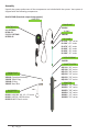
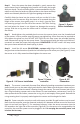
Assembly Unpack the system and ensure all the components are included with the system. Your system is shipped with the following components: BLACKCOMB (Standard output lamp systems) LAMP KEY CONTROLLER 4.1 SYSTEMS RC-B4.01 5.1/6.1 SYSTEMS RC-B56.01 GLAND NUT 320006 O-RING 300038 UV LAMP RL-210- “-02” series RL-290 “-03” series RL-470 “-06” series RL-820 “-10” series RL-850 “-20” series RL-999 “-15” series SLEEVE SPRING 310039 GLOW PLUG (BLACKCOMB5.
BLACKCOMB-HO (High output lamp systems) LAMP KEY CONTROLLER 4.1 SYSTEMS RCHO-B4.12 (fits all units) 5.1/6.1 SYSTEMS RCHO-B56.12 (fits all units) GLAND NUT 320006 O-RING 300038 UV LAMP RL-210HO “-05” series RL-330HO “-10” series RL-420HO “-15” series RL-600HO “-25” series RL-950HO “-40” series GLOW PLUG (BLACKCOMB5.1 units only) 300016 Complete Assembly 310026 Teflon Plug 310040 O-Ring 390007 Brass Nut UV SENSOR (BLACKCOMB6.1 units only) RSHO-B3.5 Standard series RSHO-B3.
System Sizing All LUMINOR UV systems are rated for a specific flow rate in water that meets the quality parameters on page 5. PLEASE NOTE that increasing the flow above this rating or disinfecting** water that does not meet the quality parameters will decrease the dose and therefore compromise the efficacy of the system. If you need to determine your maximum flow rate, you can fill a 1 gallon bucket with water and time how long it takes to fill up.
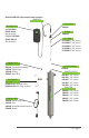
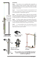
Installation Step 1: The reactor can be installed either horizontally or vertically using the clamps provided. Vertical installation is the preferred method with the inlet at the bottom (lamp connection at the top) as it allows any air that may be in the lines to be easily purged from the system. Step 2: The use of a by-pass assembly is recommended as it will allow you to isolate the UV reactor. This will allow for easier access in case maintenance is required (See Figure 4).
Step 6: Once the system has been plumbed in, gently remove the quartz sleeve from its packaging being careful not to touch the length with your hands. The use of cotton gloves is recommended for this procedure as oils from the hands can leave residue on the sleeve and lamp which can ultimately block the UV light from getting to the water. Carefully slide the sleeve into the reactor until you can feel it hit the opposite end of the reactor.
Step 11: Always hold UV lamps by their ceramic ends, not by the lamp quartz. Remove the lamp from its packaging. Again, the use of cotton gloves is recommended. Remove the lamp key from the lamp’s connector and set it aside for the next step. Be careful to not touch the key’s exposed contacts. Insert the UV lamp into the reactor, being careful not to drop it. Figure 9a. Standard Output UV Lamp Connection Figure 9b.
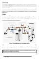
System Preparation With a new installation, or any time the UV system is shut down for service, without power, or is inoperative for any other reason, the lines in the home or facility could be contaminated. Use the following steps to prepare the lines throughout the entire home or facility. Step 1: Check for and remove any “dead ends” in the lines throughout the home as these can harbor dirt and debris. Plug in the UV system and wait until it is ready for operation.
Step 10: Dry the sleeve with separate cloth. Step 11: Replace the o-ring and slide the sleeve back into the reactor following steps 7 and 8 from the installation section of the manual. Cleaning the UV Sensor Depending on the water quality, the UV sensor may require periodic cleaning. At a minimum, the UV sensor should be cleaned on an annual basis. The following steps outline a basic cleaning procedure.
BLACKCOMB4.1 Controllers LBH4 Series LB4 Series Simplistic in operation, these systems feature a tri-colour LED that indicating system status and a 4-digit display to indicate lamp life remaining. Pressing the button will change the display to indicate total running time. When the UV lamp is on and within its operating age, the LED will be green. When the UV lamp is not on or the lamp life has expired, the LED will be illuminated red and an audible buzzer will be sounding.
A final module screen is displayed showing which specific modules were initialized. The controller then displays the lamp optimization screen for 60 seconds to allow the lamp to reach its optimum output. Finally, a final “start-up complete” screen is displayed. The system will now be ready to disinfect** water flow. all detected modules lamp reaching max output successful start-up BLACKCOMB5.1 Operational Screens On systems without the UV monitor, the default screen shows the LUMINOR Home Screen.
audible chirp every 15 seconds audible chirp every 15 seconds constant audible alarm cycles with red low UV screen Lamp Countdown Sequence The system counts down the number of days until a lamp change is required. BLACKCOMB6.1 BLACKCOMB5.1 BLACKCOMB4.1 At thirty days remaining, the LED or display screen will change to a yellow caution indicator. At seven days remaining, the system will additionally repeat an audible chirp.
System Service Suggested BLACKCOMB 5.1 & 6.1 controllers will display the System Service Suggested Screen every 6 months to remind consumers to maintain both their UV and other prefiltration. This will serve as a prompt only and will not put the system into alarm. To clear this condition simply press the button located below the screen. Lamp Replacement (BLACKCOMB4.1 systems) After the lamp is expired, it must be replaced with the same part number as indicated by the label on the reactor.
System Troubleshooting Hard Alarms: The following give a constant audible alarm. If present, the solenoid valve is closed, and the 4-20, remote alarm and wifi modules transmit the alarm. System Display Problem Resolution Reset lamp protection circuit -unplug unit for 10 seconds. The system has detected Replace the lamp with the a problem with the part as indicated on the lamp. silver label on the reactor or on the Maintenance parts screen.
Soft Alarms: The following remaining errors give a 15 second audible chirp only System Display Problem Resolution Ensure all modules are connected properly to the system and to each other. The module indicated is no longer communicating to with the system. Modules can be tested individually by plugging in one at a time and cycling power to the system. Replace any module that is not detected when plugged directly into the controller.
Temperature Management Devices Your LUMINOR BLACKCOMB system is designed to run continuously to ensure optimal disinfection**. However, during periods when no water is drawn through the system, the energy from the disinfection** process can cause the temperature of the water inside the chamber to rise. In extreme situations elevated water temperature or the fluctuation in temperature can lower the output of the UV lamp.
SOLENOID CONNECTION MODULE: Connects a NORMALLY CLOSED line voltage solenoid valve to the controller. Maximum contact rating is 240VAC (50-60Hz) / 30VDC / 2A. On a non-monitored system, the solenoid will only close on a lamp failure error. On a monitored system, the solenoid is closed when the UV level drops below 50%. Also note that in cases where emergency use of untreated water is required, the controller can be placed into a manual override mode allowing for the flow of water in an alarm condition.
BLACKCOMB Standard Output System Specifications LUMINOR EQUIPMENT SPECIFICATIONS Multi-Use / Residential systems (standard output lamps) MODEL NSF Class A Flow Rate 40mJ/cm2 @ 70% UVT (add “A” suffix on LB6 models) NSF Class B Flow Rate 16mJ/cm2 @ 70% UVT (“B” suffix on LB5,LB6 models) Flow Rate 16mJ/cm2 @ 95% UVT Flow Rate 30mJ/cm2 @ 95% UVT Flow Rate 40mJ/cm2 @ 95% UVT Port Size Electrical Plug Type Lamp Power (Watts) Power (Watts) Replacement Lamp Replacement Sleeve Reactor Dimensions Chamber Material
BLACKCOMB-HO High Output System Specifications LUMINOR EQUIPMENT SPECIFICATIONS Residential Crossover systems (high output lamps) MODEL NSF Class A Flow Rate 40mJ/cm2 @ 70% UVT (add “A” suffix on LBH6 models) NSF Class B Flow Rate 16mJ/cm2 @ 70% UVT (“B” suffix on LBH5,LBH6 models) Flow Rate 30mJ/cm2 @ 95% UVT Flow Rate 40mJ/cm2 @ 95% UVT Flow Rate Hot Water (-HW suffix) model 30mJ/cm2 @ 75% UVT Flow Rate Low UVT (-50 suffix) model 30mJ/cm2 @ 50% UVT Flow Rate TOC (-TOC suffix) model 150mJ/cm2 @ 98% UVT P
Performance Data Sheet (on all NSF/ANSI Standard 55, Class A Systems) C US System Tested and Certified by NSF International against CSA B483.1 and NSF/ANSI 55 for Disinfection** Performance, Class A LB6-02XA Model NSF Class A Flow Rate 1.6 gpm (40mJ/cm2 @ 70% 6.1 lpm 0.4 m3/hr UVT) Port Size LB6-03XA LB6-02A-12V LB6-03A-12V LB6-02A-24V LB6-03A-24V ½”FNPT Electrical Operating Pressure Operating Water Temperature 2.2 gpm 8.3 lpm 0.
Performance Data Sheet (on all NSF/ANSI Standard 55, Class B Systems) C US System Tested and Certified by NSF International against CSA B483.1 and NSF/ANSI 55 for Disinfection** Performance, Class B Model LB5-03XB LB5-06XB LB5-10XB LB5-15XB LB6-06XB LB6-10XB LB6-15XB LBH5-05XB LBH6-06XB LBH5-10XB LBH6-10XB LBH5-15XB LBH6-15XB LBH5-25XB LBH6-25XB LBH5-40XB LBH6-40XB NSF Class B Flow Rate (16mJ/cm2 @ 70% UVT) 5.2 gpm 11 lpm 1.2 m3/hr 7.6 gpm 29 lpm 1.7 m3/hr 13 gpm 49 lpm 3.
Limited Warranty Statement: Products manufactured by LUMINOR Environmental Inc., (LUMINOR) are warranted to the original user only to be free of defects in material and workmanship for a period as specified below. This warranty only applies to the original purchaser and is not transferable. UV SYSTEMS Ten (10) year Limited Warranty on the stainless steel reactors, from the date of original purchase, or installation (proper documentation required for verification).
TO GET WARRANTY SERVICE To obtain service under this warranty, you must first contact where the product was originally purchased to obtain a Warranty Return Authorization. You will require proof of purchase and installation date, failure date, and any other requested data. Unless otherwise provided, the Dealer or Distributor will contact LUMINOR for instructions on returning the product.
illuminating technologies for life 80 Southgate Drive, Unit 4 Guelph, Ontario, CANADA N1G 4P5 P: 519-837-3800 TF: 855-837-3801 F: 519-837-3808 info@luminoruv.com www.luminoruv.