
Hardware User (IVD) Instruction Manual

Luminex IVD MAGPIX Hardware Installation and User Manual
40
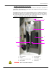
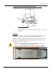
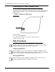
Sample Probe Assembly
The stainless steel sample probe fits inside a holder. A probe fitting screws into the top of
the holder, keeping the probe in place. From the probe, through the fitting, extends a tube
that passes through a strain relief and attaches to the sample valve. The sample loop from
the syringe pump also enters the sample value, and a tube extends from it into the optical
chamber, carrying the sample mixed with Drive Fluid.
A wheel pulley, covered by a protective shield, moves the probe assembly along the x
ax
is.
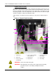
FIGURE 44. Sample Probe
1
2
3
5
6
4
7
8
9
Assembly
WARNING: Avoid contact with moving parts.
WARNING: Wear appropriate personal protective equipment when handling
parts that come into contact with potentially biohazardous
samples.
1 Sample loop 4 Valve-to-optical chamber
tube (coded red)
7 Protective cover on
wheel pulley
2 Strain relief 5 Sample probe 8 Probe holder
3 Probe-to-valve tube
(coded black)
6 Sample valve 9 Probe fitting