® FLEXMAP 3D Hardware User Manual
Copyright Information © Luminex Corporation, 2011. All rights reserved. No part of this publication may be reproduced, transmitted, transcribed, or translated into any language or computer language, in any form or by any means without prior express, written consent of Luminex Corporation. LUMINEX CORPORATION 12212 Technology Boulevard Austin, Texas 78727-6115 U.S.A. Voice: (512) 219-8020 Fax: (512) 219-5195 Luminex® FLEXMAP 3D® Hardware User Manual PN 89-00002-00-187 Rev C November 2011 MDCI Ltd.
Standard Terms and Conditions for Use of Instrument Product By opening the packaging containing this product ("Product") or by using such Product in any manner, you are consenting and agreeing to be bound by the following terms and conditions. You are also agreeing that the following terms and conditions constitute a legally valid and binding contract that is enforceable against you.
hardware not provided by Luminex. If Product is purchased from a Luminex authorized reseller, any warranty obligations shall be provided in writing directly by such Luminex authorized reseller to Buyer. THIS WARRANTY IS EXCLUSIVE AND LUMINEX MAKES NO OTHER WARRANTY, EXPRESS OR IMPLIED, INCLUDING WITHOUT LIMITATION ANY IMPLIED WARRANTY OF MERCHANTABILITY OR FITNESS FOR A PARTICULAR PURPOSE.
indicated on the Product label, the Product has not received approval from the United States Food and Drug Administration or other federal, state or local regulatory agencies and have not been tested by Seller or Luminex for safety or efficacy in food, drug, medical device, cosmetic, commercial or any other use, unless otherwise stated in Seller's technical specifications or material data sheets furnished to Buyer.
contract or any other theory of law or equity arising out of, directly or indirectly, the use of the Product or by reason of Buyer's failure to perform its obligations contained herein.
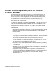
End-User License Agreement (EULA) for Luminex® xPONENT® Software This Luminex End-User License Agreement (“EULA”) is a legal agreement between you (either an individual or a single entity, also referred herein as “you”) the end-user and Luminex Corporation (“Luminex”) regarding the use of the xPONENT software product provided to you above, which includes computer SOFTWARE and online or electronic documentation and may include associated media and printed materials (if any) (“SOFTWARE”).
3. GRANT OF LICENSE. Subject to the terms and conditions of this EULA, Luminex hereby grants to you a nonexclusive, nontransferable, nonassignable license (without right to sublicense) under Luminex's copyrights and trade secrets to use the SOFTWARE on a single computer running with a single unit of a specific model of Luminex instrument, as such model is identified on the packaging included with the SOFTWARE. You may make one (1) copy of the SOFTWARE for backup or archival purposes only.
5. TERM AND TERMINATION. Your rights under this EULA are effective until termination. You may terminate this EULA at any time by destroying the SOFTWARE, including all computer programs and documentation, and erasing any copies residing on your computer equipment. Luminex may terminate this EULA upon thirty (30) days written notice to you. Your rights under this EULA automatically terminate without further action on the part of Luminex if you do not comply with any of the terms or conditions of this EULA.
Table of Contents Chapter 1 Safety ..................................................................................................................1 Intended Use ...............................................................................................................................................1 Warnings and Notes ....................................................................................................................................1 Symbols .........................................
Chapter 3 Maintenance and Cleaning .............................................................................23 General Maintenance Precautions ............................................................................................................ 23 Daily Maintenance .....................................................................................................................................23 Initializing the FLEXMAP 3D Instrument ............................................................
Chapter 1: Safety Become familiar with the information in this chapter before using the equipment. Do not perform procedures on your system that are not specifically contained in this manual, unless you are directed to do so by Luminex Technical Support. Intended Use The Luminex® FLEXMAP 3D® system is a multiplex test system intended to measure and sort multiple signals generated in an assay from a sample.
Symbols You may encounter these symbols during the use and operation of the Luminex® FLEXMAP 3D® system. They represent warnings, conditions, identifications, instructions, and regulatory agencies. Warning symbols are further explained in the Safety Precautions section.
Testing and Certification The FLEXMAP 3D system has been tested by MET. FIGURE 1. MET Mark In addition, Luminex FLEXMAP 3D complies with European Union (EU) safety requirements and therefore may be marketed in the Europe Single Market. The following European Union compliance label appears on the back of the FLEXMAP 3D instrument. FIGURE 2. European Union Compliance Label Safety Precautions Read the following safety information before using the FLEXMAP 3D instrument.
General CAUTION: Keep access doors closed during normal operation. Always observe standard laboratory safety practices. Electromagnetic Compatibility The FLEXMAP 3D system complies with the emission and immunity requirements described in and . The electromagnetic environment should be evaluated prior to operation.
FIGURE 4. Avoid Exposure Label All Class 3b laser apertures are located within the FLEXMAP 3D instrument and are contained within a protective housing, accessible only to trained field service technicians. When performing routine maintenance, turn power to the system off and disconnect the power cord. DANGER: Do not, under any circumstances, remove the FLEXMAP 3D instrument cover.
salts” (Centers for Disease Control, Atlanta, Georgia, April 30, 1976). Biological Samples Human and animal samples may contain biohazardous infectious agents. Where exposure to potentially biohazardous materia exists, follow appropriate biosafety procedures and use personal protective equipment (PPE). PPE includes gloves, gowns, laboratory coats, face shields or mask and eye protection, respirators, and ventilation devices.
Electrical Components Do not perform any maintenance or cleaning of the electrical components in the system, with the exception of replacing fuses. The following fuse caution label appears on the back of the FLEXMAP 3D. FIGURE 5. Fuse Caution Label The following voltage label appears on the back of the FLEXMAP 3D instrument. It displays the FLEXMAP 3D serial number, model number, power requirements, and manufacturer’s information. FIGURE 6.
Heat The heater plate, used to warm the heater block of the XY platform, can be heated between 35°C and 60°C. WARNING: The heater plate of the FLEXMAP 3D XY platform may be hot and can cause personal injury if touched. Do not touch the heater plate. Decontamination Procedure Occasions may arise when it becomes necessary to decontaminate the entire Luminex® FLEXMAP 3D® instrument, for example, prior to shipping.
FIGURE 7. Installed FLEXMAP 3D System Disposal of Instrument Within the European Union, the Waste Electrical and Electronic Equipment Directive 2002/96/EC requires that you properly dispose of electrical and electronic equipment when it reaches its end of life. If you are disposing of a Luminex® FLEXMAP 3D® instrument, decontaminate the system. See the section titled “Decontamination Procedure”.
FLEXMAP 3D® Hardware User Manual 10
Chapter 2: Technical Overview This chapter reviews the technical aspects of theLuminex® FLEXMAP 3D® system: operation, system components, subsystems, recommended additional equipment, and specifications. How the FLEXMAP 3D System Operates The Luminex® FLEXMAP 3D® system, in combination with xMAP® (Multi-Analyte Profiling) technology, will simultaneously measure up to 500 analytes from a single sample.
Electronics The electronics system provides the power for operation and control of the FLEXMAP 3D system and communication between its parts. Power Input Module The power input module contains the input power plug and fuses. This is the protective earthing point for the FLEXMAP 3D system. The mating power cord connector type is IEC-320-C13. The mating power cord provides electrical power to the instrument when it is connected to an electrical outlet and is the means of disconnection.
1 Power Input Module 2 Communications Port P1 (USB type B) Fluidics The fluidics system handles the flow of liquid through the Luminex® FLEXMAP 3D® instrument. Access Doors The Luminex® FLEXMAP 3D® system has two front access doors. The left door supplies access to a door ventilation filter and the sheath filter. The right door supplies access to a door ventilation filter, the sample probe, and the syringe pumps. See the "Front of the FLEXMAP 3D Instrument" image below. FIGURE 9.
Cheminert® Fitting This fitting attaches the sample probe to the sample tubing. Disconnect this fitting when you remove the sample probe. See the "Sample Probe" figure below. WARNING: Wear appropriate personal protective equipment when handling parts that come into contact with potentially biohazardous samples. FIGURE 10.
FIGURE 11. Syringe Pump 1 Syringe arm (within dotted lines) 2 Glass syringe barrel 3 Syringe plunger Sheath Filter The sheath filter removes particles greater than ten microns in diameter from the sheath fluid. See the "Fluidics Bay" image below. Fluidics Bay The waste and sheath connectors, located on the front of the fluidics bay, connect to the sheath fluid and waste fluid containers using clear tubing. The sheath fluid connector is blue and the waste connector is orange.
FIGURE 12. Fluidics Bay 1 Sheath filter 2 Tubing to sheath fluid container is attached here (blue) 3 Tubing to waste fluid container is attached here (orange) Waste Fluid Container The waste fluid container receives waste from the system. To maintain a stable flow rate, do not move the waste line or container during system operation and make certain the waste fluid container is properly vented. Place the container at least three feet below the surface on which the instrument rests.
of this manual. The "Fluidics Bay" image above and "Front Door Ventilation Filters" image below show the location of these filters. FIGURE 13. Front Door Ventilation Filters View A Right front door, viewed from inside View B Left front door, viewed from inside 1 Filter 2 Holding clamp FIGURE 14.
2 Holding clamp 3 Cover over HEPA air filter Optics The optical system consists of the optical assembly and the excitation lasers. The optical components do not require manual adjustment by the user. System Components The following topics describe details of the three components of the Luminex® FLEXMAP 3D® system: software, reagents, and hardware. Luminex xPONENT® 4.0 Software Luminex xPONENT 4.0 software provides complete control of the Luminex® FLEXMAP 3D® instrument and performs the analyses.
CAUTION: Adhere to standard laboratory safety practices when handling hazardous, toxic, or flammable reagents and chemicals. Contact Luminex Technical Support when in doubt about compatibility of cleaning and decontamination agents or materials. Required Laboratory Reagents • 10 - 20% household bleach • 70% isopropanol or 70% ethanol • 0.1N NaOH • Mild detergent • Distilled water WARNING: Isopropanol and ethanol are flammable liquids.
Uninterruptible Power Supply (UPS) or Surge Protector Luminex recommends using either an uninterruptible power supply (UPS) or a surge protector to protect your system from power outages. Use a UPS that provides 1300 watts for at least 45 minutes. Select a surge protector that fits your requirements with regard to electrical environment, endurance, suppressed voltage rating, and method of protection. The surge protector requires three outlets and a minimum rating of 1500 watts.
Pollution degree 2 Operating temperature: 15°C to 30°C (59°F to 86°F) Operating humidity: 20% to 80%, noncondensing Shipping and storage temperature: 0 to 50°C (32° F to 122° F) Shipping and storage humidity: 20% to 80%, noncondensing Temperature control: Maintains samples using the heater block at a constant temperature from 35°C to 60°C (95°F to 131°F), +/- 1°C of setpoint. Altitude: Operation up to 2400 m (7874 ft.
Classification detector: Avalanche photo diodes with temperature compensation Doublet discrimination detector: Avalanche photo diodes with temperature compensation Fluidics Cuvette: 200 micron square flow channel Sample injection rate: 2 μL/second Sample uptake volume: 20 to 200 μL Sheath flow rate: 7.9 (+/- 0.
Chapter 3: Maintenance and Cleaning To ensure accurate test results, properly clean and maintain the Luminex® FLEXMAP 3D® system. Read and follow all instructions in this section. Perform adequate maintenance and cleaning to avoid inaccurate results and potential hazards.
Most of the daily maintenance tasks for the FLEXMAP 3D system, including system initialization, warmup, and shutdown, can be performed using available software commands. For details about the performance of these activities, see the appropriate Luminex software manual or Luminex online help. Initializing the FLEXMAP 3D Instrument Use the software to perform system initialization.
overflow. Empty the waste fluid container each time you replace or fill the sheath fluid container. Place the waste fluid container at least three feet below the surface on which the FLEXMAP 3D instrument rests. Do not place the waste fluid container on top of the instrument. Do not move the waste line vertically while the FLEXMAP 3D instrument is running. Contact Luminex Technical Support before relocating the waste fluid container or rerouting the waste line.
Removing Clogs If you frequently use the FLEXMAP 3D system to test concentrated serum or other debris ridden samples, Luminex recommends that you use the software to perform a clog removal routine weekly. Luminex recommends using sodium hydroxide (NaHO) to perform an alcohol flush of the FLEXMAP 3D instrument to remove clogs. To remove clogs: 1. Replace the alcohol in the alcohol well of the reservoir area with a 0.1N sodium hydroxide solution. 2. Use the software to perform a clog removal routine.
4. Replace the sample probe and tightly screw in the Cheminert fitting. 5. Use the software to perform an automatic probe height adjustment. NOTE: Perform an automatic probe height adjustment any time the probe is . FIGURE 15. The Sample Probe Calibrating the FLEXMAP 3D System Calibrate the FLEXMAP 3D system weekly as part of regularly scheduled maintenance. There are several different ways to calibrate the system using the software.
1. Turn off the FLEXMAP 3D instrument and unplug the power cord. 2. Wipe all exterior surfaces with mild detergent, followed by a household bleach solution diluted to 10% to 20%, followed by distilled water. 3. Open both doors of the instrument. 4. Clean all accessible surfaces with detergent, followed by the household bleach solution (10% to 20%), followed by distilled water. WARNING: Avoid contact with the tubing and electronic parts of the instrument. 5.
13. Use the software to run the prime command twice, watching for any leaks in the syringe area. 14. Close the right front door. FIGURE 16. Syringe Assembly (Inside Right Door) Replacing the HEPA Air Filter The HEPA air filter is the round filter behind the panel on the left side of the front of the fluidics bay. Tubing from the interior of the fluidics bay is attached to the stem in the center back of the filter. To replace the HEPA air filter: 1.
5. Remove the filter with one hand and hold the tubing with the other hand. CAUTION: Do not allow the tubing to fall inside the instrument. 6. Connect a new filter to the tubing and position the filter inside the panel. 7. Reattach the panel door to the unit and close the access door. 8. Plug in the power cord and turn on the FLEXMAP 3D instrument. FIGURE 17. HEPA Air Filter Cleaning the Ventilation Filters Each filter has at least one imprinted arrow on its metal frame.
6. Stand the filters upright to air dry. CAUTION: Filters must be completely dry prior to reinstallation. 7. Reinstall filters. The arrows on the door filters should point to the inside of the door. The arrow on the XY filter should point up. 8. Reinstall the XY cover and close the access doors. 9. Plug in the power cord and turn on the FLEXMAP 3D instrument. FIGURE 18. Ventilation Filter on XY Platform FIGURE 19.
Annual maintenance requires replacing the sheath filter. To replace the Luminex® FLEXMAP 3D® instrument sheath filter: 1. Turn off the FLEXMAP 3D instrument and unplug the power cord. 2. Open the left door on the FLEXMAP 3D instrument and locate the sheath filter on the front of the fluidics bay. 3. Disconnect the filter by pushing down on the metal clamps at each quick-disconnect point.
Storing the FLEXMAP 3D Instrument Storing the FLEXMAP 3D Instrument This procedure explains the steps you should take before placing the FLEXMAP 3D instrument into long-term storage. To prepare the FLEXMAP 3D instrument for storage: 1. Use the software to perform a Preparation for storage routine. 2. Remove the sample probe from the instrument and flush it with distilled water from the narrow end out through the larger end. 3.
DANGER: To avoid serious injury or death by electric shock, you must turn off the FLEXMAP 3D instrument and unplug it from the wall before replacing a fuse. To replace a fuse: 1. Unplug the power cable from the instrument. 2. Use a small, flat-blade screwdriver to open the module door on the lower left corner of the back of the instrument. The door opens downward. Inside are two cartridges, a red one on top and a black one on the bottom. 3. Use the screwdriver to remove the red cartridge. 4.
Maintenance Logs Reproduce the following forms as necessary and use them to record maintenance information. Fill in the dates in the first line of the table. The first table includes a sufficient number of columns for one week (7 days). The second table includes a sufficient number of columns for monthly maintenance (one task monthly), semi-annual maintenance (two tasks twice yearly), and annual maintenance (two tasks yearly).
Semi-annual Maintenance Clean ventilation filters Replace HEPA air filter Replace syringe seals Annual Maintenance Replace sheath filter FLEXMAP 3D® Hardware User Manual 36
Chapter 4: Troubleshooting Troubleshooting procedures help users identify and remedy problems with the instrument. Overview To troubleshoot a problem, locate the symptom in one of the tables in this chapter, determine the cause from the listed possibilities, and remedy it with the provided solution.
Power Supply Problems Power supply problems often involve a blown fuse, faulty electronic component, or disconnected cable. CAUTION: Whenever you deal with a potential electrical problem, be careful to avoid electrical shocks. TABLE 1. Power Supply Problems Symptom Possible cause Solution The FLEXMAP 3D instrument will not turn on. The power cord is disconnected. Plug in the power cord. No voltage is coming from the electrical outlet. Verify that the electrical outlet is operational.
Clogs Often, a clog somewhere in the Luminex® FLEXMAP 3D® instrument is the cause of a fluid leak, a pressurization or sample probe problem, or a problem with calibration, verification, or data acquisition. To determine whether there is a clog, check the bead count during calibration. During calibration you should see 300 bead events per second or more. If there are fewer than that, there is probably a clog in the instrument.
Fluid Leaks Fluid leaks can result in poor pressurization and failed sample acquisition. TABLE 4. Fluid Leaks Symptom Possible cause Fluid is pooled around the FLEXMAP 3D instrument. Fittings or fluid lines are damaged. Turn off and disconnect the instrument to avoid electrical shock and contact Technical Support. Fluid drips from the sample probe. The sample probe is clogged. See the section titled “Clogs”. The sample valve is faulty. Contact Technical Support. The syringe seal leaks.
Symptom Possible cause Solution The microtiter plate is warped. Inspect the microtiter plate. Replace it if it is warped. The sample probe is bent. Remove the sample probe from the instrument. Roll it on a flat surface. If a sample probe has been bent and rolled straight more than once, discard it and replace it with a new sample probe. Perform an automatic sample probe height adjustment using the software. Calibration Problems TABLE 6.
Symptom No events are collected during calibration. Possible cause Solution There is air in the instrument. The waste line was moved during instrument operation, resulting in an unstable flow rate. Perform an automatic sample probe height adjustment. Use the software to run a prime command three times, an alcohol flush command twice, then a wash command three time with distilled water. The waste line was moved during instrument operation, resulting in an unstable flow rate.
Symptom Possible cause Solution The verification lot is expired. Use an unexpired bottle of verification microspheres. The verification microspheres have been diluted. Do not dilute the verification microspheres. The sample probe height is incorrect. Perform an automatic sample probe height adjustment. The sample probe is clogged. See the section titled “Clogs”. There is air in the instrument. Verify the sample probe height.
Symptom Possible cause Solution The wrong lot number or target values are entered in the appropriate page of the software UI. Check the lot number and target values to make sure they are correct. Air is present in the instrument. Verify the sample probe height. Use the software to run a prime command three times, an alcohol flush command twice, then a wash command three times with distilled water. The acquisition volume is set too high.
FIGURE 22. TABLE 9. Normal Bead Detail Bead Detail Irregularities Symptom Description Possible Problem Solution xMAP and calibrator microspheres form a group in the wrong location. Calibrator microspheres group together at the top of the region. The calibrator microspheres are photobleached. Replace the calibrator microspheres with unphotobleached calibrator microspheres. To avoid photobleaching, protect microspheres from light. xMAP microspheres group together at the lower right of the region.
Symptom Description Possible Problem Solution xMAP microspheres do not form a cohesive group and are somewhat scattered. There is air in the instrument. Verify the sample probe height. Use the software to run a prime command three times, an alcohol flush command twice, then a wash command three times with distilled water. xMAP microspheres are widely scattered. The sheath fluid is empty. Make sure there is sheath fluid in the sheath container.
Appendix A: Shipping Shipping If a serious problem arises with the FLEXMAP 3D system, it may be necessary to return it to Luminex Corporation for repairs. If Luminex Technical Support directs you to return the FLEXMAP 3D system, the Technical Support representative will provide you with all necessary information as well as give you a Return Material Authorization (RMA) number.
6. Connect the waste fluid tubing (orange connector) to the bottom quick disconnect point (white connection) of the sheath filter tubing. 7. Use the software to run a warmup command. This starts the compressor, which drains the sheath fluid from the reservoir into the waste fluid container. NOTE: To refill the reservoir, reconnect each connector to its color-matched connection and use the software to run a prime command. FIGURE 23.
Yes No Printed Name _____________________________________________________ Signature ________________________________________________________ Company/Institution ________________________________________________ Date________________ Instrument Serial No.
FLEXMAP 3D® Hardware User Manual 50
Appendix B: Installation Installation of the FLEXMAP 3D The following installation instructions for FLEXMAP 3D are to be used for site prep, assessing facilities requirement and in the event cabling or tubing must be reconnected.
1. Place the PC and monitor on the right side of the instrument. 2. Connect the FLEXMAP 3D instrument and all necessary peripheral devices to the PC. FIGURE 24. Back of PC 1 Monitor Plug 4 Barcode Scanner Plug 2 FLEXMAP 3D Communications Plug (USB type A ) 5 Monitor Plug (Touchscreen monitors only) 3 Mouse Plug 6 Power Inlet FIGURE 25.
1 Power Inlet 2 PC Communications plug (USB type B) 3. Connect the USB communications cable between the FLEXMAP 3D instrument (P1) and the PC, and connect the power cables for the PC, monitor, and FLEXMAP 3D instrument to outlets but do not turn on any of the devices. 4. Place the sheath container below the instrument with the container opening facing up. 5. Remove the existing container cap and install the cap from the blue tubing accessory in its place. 6.
18. Calibrate the probe height using the instructions in the software user manual. NOTE: For information on calibrating the probe correctly, refer to the FLEXMAP 3D Probe Height Adjustment Tool section. 19. Calibrate the instrument using the instructions in the software user manual.
Installation 55
FLEXMAP 3D® Hardware User Manual 56
Appendix C: Part Numbers Hardware Product Description Customer Number Luminex® FLEXMAP 3D® with xPONENT 4.
Software Product Description Customer Number Luminex xPONENT 4.
Appendix D: FLEXMAP 3D Probe Height Adjustment Tool NOTE: The Probe Height Adjustment Tool is to be used for 384 well mylar bottom and 384 well filter bottom plates only.
1. Using data sheet for the plate you intend to calibrate the probe to, subtract the "well depth" from the "plate height" as shown in the example below: Plate Height: 14.2mm - Well Depth: 11.43mm = 2.77mm (2.8mm) Example 1: 2.8mm or well C7 on the probe height adjustment tool for this example. 2. Click Eject from the System Status bar to eject the XY platform. 3. Place the probe height adjustment tool on the XY platform. 4. From the Home page click Probe and Heater. 5.
2.9mm or well D7 on the probe height adjustment tool for this example.