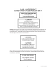
BIO-RAD LABORATORIES 2000 ALFRED NOBEL DRIVE HERCULES, CA 94547 PART NUMBER MATERIAL SPECIFICATION (Non-Chemical) REV [BAAN ITEM NUMBER] 10005042 C EXTENDED DESCRIPTION: Hardware User’s Manual Bio-Plex 200 System ERP/PLM DESCRIPTION (30 Characters Max): USER’S MANUAL BIO-PLEX SYSTEM SPECIFICATIONS (ALL DIMS ARE REF ONLY) Manual is printed from the PDF file, 10005042C_BIOPLEX_HARDWARE_MANUAL.PDF. Dimensions of the manual are 8.5 inch wide by 11.0 inch tall.
Table of Contents Page Section 1 General Information ......................................................................1 1.1 1.2 About This Manual ....................................................................................1 Safety Information .....................................................................................1 1.2.1 Electrical Safety Information ...........................................................2 1.2.2 Laser Safety Information .....................................
Section 1 General Information 1.1 About This Manual A Bio-Rad service engineer will install the Bio-Plex® 200 system. However, the procedure is provided herein as a reference, in addition to instructions for maintaining your Bio-Plex 200 system. This manual uses certain conventions to facilitate understanding of the text material and to assist operators in using the Bio-Plex 200 system.
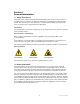
1.2.1 Electrical Safety Information Warning: This instrument must be connected to an approved power source. Warning: Do not perform any maintenance or cleaning of the electrical components (except for fuses) of this instrument. Warning: This system contains fluidics. In the event of a fluid leak, turn off all power to the system and disconnect all power cords. Contact Bio-Rad Technical Support for further information. Note: Waste levels must be manually monitored.
Caution: Removal of the array reader cover is intended for trained service personnel only. Do not attempt to operate the instrument with the cover removed. When routine maintenance is performed, power to the instrument must be OFF and the power cord must be disconnected. This label appears on the back of the instrument: All laser apertures are located within the instrument and are contained within a protective housing.
1.2.3 Mechanical Safety Information Caution: During operation, this system contains exposed, moving parts. Risk of personal injury is present. Keep hands and fingers away from the sample probe and the syringe arm, as well as the microplate platform during operation. Note: Access doors must be closed while operating the Bio-Plex 200 system. 1.2.4 Biological Safety Information Warning: All human and animal samples may contain hazardous infectious agents.
2.
Table 1. Array Reader Front and Side Panel Features. Feature Sample arm Description The sample arm transports the sample from the 96-well microtiter plate in the microplate platform to the cuvette. Upon operation, the carriage drops automatically to the microtiter plate for sample retrieval. Sample needle A stainless-steel sample needle acquires sample from the 96-well plate in the microplate platform.
Table 2. Array Reader Rear Panel Features. Feature Communications port P1 Description The DB9-PIN connector is used to connect the array reader to the computer. Communications port P2 The DB9-PIN connector is used to connect the array reader to an HTF. Air filter and access door A replaceable filter cleans the air used to pressurize sheath fluid. This filter is enclosed behind an access door. Refer to the Care and Maintenance section (page 27) for routine maintenance procedures.
2.2.2 Microplate Platform The microplate platform (Figures 4 and 5) allows the automated processing of samples from a 96-well microplate. The features of the microplate platform are outlined in Table 4. Blue shipping pin Access door Fig. 4. Microplate platform – front view. Power connector Communications port Fig. 5. Microplate platform – back panel view. Table 4. Microplate Platform Features. Feature Access door Description This door provides access to the assay plate holder.
2.2.3 High-Throughput Fluidics (HTF) The Bio-Plex HTF (high-throughput fluidics) is designed to automate the introduction of sheath fluid into the array reader (Figures 6 and 7). With the HTF, you can run samples continuously without the need to replenish the sheath supply. The HTF automatically draws sheath fluid from a nonpressurized bulk container to constantly maintain a reservoir of pressurized sheath fluid.
2.2.4 Computer and Monitor The Bio-Plex 200 system may be supplied with a computer. If so, please transfer the computer’s registration to your company’s name following unpacking. 2.2.5 Maintenance, Calibration, and Validation Plate The Bio-Plex maintenance, calibration, and validation (MCV) plate IV (Figure 8) is a specially designed accessory to facilitate automated system startup, calibration and shut-down procedures, as well as validation routines used to qualify the performance of the array reader.
2.3 Recommended Additional Equipment Not Provided Surge protector We recommend the use of a 6-outlet surge protector, with a minimum surge current of 12,000 A; power, 1,500 W; clamping voltage, 336 V; clamping response, <500 psec; maximum leakage current, <50 µA. UL-listed (for USA user), CSA-certified, CE-marked (for use outside USA). See www.alliedelec.com and part number 575-9715.
4. The maximum distance between the computer and the microplate platform and array reader should be 1.5 m (5 ft), the length of the communications cable supplied with the instruments. 5. Do not place any items on top of the array reader. The cover is not designed to support objects and thus the optics could be damaged. 6. If installing the HTF, allow an area ~3 ft below the array reader for the 20 L sheath fluid cube.
• • • • Communication cable Sheath fluid bottle Sheath fluid waste bottle 1 sample needle (11.6 cm/4.6 in) 1. Unpack all components, being careful not to jar the array reader. Ensure that all accessories are supplied. 2.
Reader communication USB port Reader communication port P1 (upper port) HTF communication port P2 (lower port) Microplate platform port Microplate platform serial port Fig. 12. Completed connections of computer and monitor to the Bio-Plex suspension array system. 3.5 Connecting the Sheath Fluid and Waste Containers 1. Attach the 1.5 L waste bottle (orange-ringed cap) to the orange Waste connector on the left side of the array reader. An audible click indicates proper connection.
Empty when waste fluid reaches this level Fill when sheath fluid reaches this level Fig. 13. Waste and sheath fluid bottle connections. Note: To set up the 20 L sheath fluid cube container for use, remove tape from box and lift off the round white cover. Pull spout out of the box. Unscrew cap and replace it with the spigot cap included in the box. Note: The waste bottle must be emptied and the sheath bottle must be refilled after reading two assay plates.
2. Insure that the array reader, microplate platform, and HTF unit are turned off. 3. Insert the Bio-Plex Manager CD-ROM into the CD drive of the computer. 4. Select Install Bio-Plex Manager. 5. After installation, remove the installation disk. 6. Attach the HASP key. 7. Reconnect the USB communication cable and turn on the array reader, microplate platform, and HTF unit. Note: Please refer to the Bio-Plex Manager software manual for detailed installation instructions. 3.7.
Knurled tubing connector Sample arm Needle height adjustment thumbscrew Long sample needle (11.7 cm/4.6 in) Fig. 15. Sample needle assembly. 4. Remove the sample needle by grasping the needle and gently pushing up. 5. Insert the new needle into the sample arm, making sure it aligns with the needle guide. If the needle is not aligned into the needle guide, carefully reposition the array reader to align the needle and the needle guide.
Fig. 16. Sample needle dialog. 5. Click Eject/Retract to eject the plate holder. 6. Place the MCV plate on the microplate platform with the black arrow facing toward the array reader. 7. Click on the Eject/Retract button to retract the plate. 8. Tape the access door of the microplate platform open. It will be necessary to be able to see inside the access door. 9. In the Adjust Needle window, click on the Up/Down button. The needle will move to the down position. 10.
Needle height adjustment thumbscrew Fig. 17. Sample needle assembly. 11. By holding onto the needle height adjustment thumbscrew on the needle arm, manually move the needle so that it just touches the bottom of the needle adjustment well of the MCV plate. Move the needle up and down gently a couple of times to verify that the needle is barely touching the bottom of the well. 12. Tighten the needle height adjustment thumbscrew so that it is no longer possible to manually move the needle up and down.
2. Click the Eject icon. Insert the MCV plate into the microplate platform. Click Retract. 3. Choose Instrument from the main menu bar. Choose Additional Functions, followed by Prime. 4. Inspect the waste line outside the instrument for air pockets. Repeat the priming procedure until no air pockets are observed in the waste line outside of the array reader. This may require a few priming cycles. 5. Choose Instrument from the main menu bar. Choose Additional Functions. Choose Alcohol Flush.
Fig. 19. Device status window. 6. After the pressure has stabilized, record the air and sheath pressure (Figure 19, arrows). Air pressure: ________ psi Sheath pressure________ psi Save this information. You will need it later in the installation procedure, and you will also need to refer to it if you use the array reader with the original sheath fluid container again. 7. At the end of the prime cycle, disconnect the sheath fluid container. Store it in a safe place.
Fig. 20. HTF setup. 9. Make the following connections to connect the HTF to the array reader: • Connect the sheath fluid line (blue fitting) to the Sheath Out connector on the front of the HTF.
Note: You may use the additional waste line provided with the system to drain to a larger waste container. The large waste container waste must be positioned so that it is no more than 3 or 4 ft below the array reader. Please note that the instrument flow rate is influenced by waste container placement, which may affect performance. 10. Lower the stainless-steel filter end of the sheath fluid line to the bottom of a full box of sheath fluid. Secure the cap on the sheath fluid box.
15. Because the flow rate in step 14 is adjusted by altering the system pressure, it is necessary to repeat steps 3 to 5 of Section 3.10 (Resetting Instrument Pressure Settings). Note: It is necessary to run the Reset Instrument Pressure Settings utility whenever the flow rate (or system pressure) is changed. This is a rare occurrence in normal operation. 3.
1 Make sure that the system has been set up according to the directions in the Millipore user guide. Hint: Make sure that the connector leading to the vacuum control knob is perpendicular to the manifold. This will ensure that no buffer travels to the vacuum control knob. 2 Place a 96-well flat-bottom microplate (not a filter plate) on the vacuum apparatus. 3. Make sure the gold vacuum control valve (Figure 23) is completely open (all colors showing). 4.
3. Turn on the laboratory vacuum to maximum level (the same level that was used in the preceeding calibration procedure). 4. Press on the filter plate and note the time required to evacuate the solution from the wells. The time required should be 2–5 sec. Note: It is important to perform this step exactly as you would perform a wash step in a Bio-Plex assay. 5. If the time required to evacuate the solution from the wells was less than 2 sec, the calibrated pressure is too high.
Section 4 Care and Maintenance Table 6. Summary of Care and Maintenance. Daily Startup, calibrate, wash between plates, shut down Weekly Sonicate needle, unclog, check for leaks Monthly Validation, clean exterior surface 6 months Replace syringe seal, clean ventilation filter Yearly Replace sheath filter, replace air intake filter Note: Two long needles are included with the Bio-Plex® 200 system.
Every Month Clean exterior surfaces Disconnect the instrument from AC power by turning off the power switch on the rear of the array reader and microplate platforms. Unplug both instrument power cords from the wall source. Wipe all exterior surfaces with mild germicidal detergent, followed by a 10% bleach solution. Open both front doors of the array reader and clean all accessible surfaces with detergent followed by a 10% bleach solution. Dry the sheet metal surfaces to prevent corrosion.
Air intake filter Note: Hold on to the tubing! Do not allow the tubing to fall inside the instrument. Replace the air intake filter every year. Disconnect the instrument from AC power by turning off the power switch on the rear of the array reader. Unplug both instrument power cords from the wall source. Looking at the back of the array reader, locate the panel at the top left. Remove the screw at the top of the panel and open the panel door. Pull the filter 3–4 in from the unit. Grasp the tubing.
Section 5 Troubleshooting 5.1 Troubleshooting Guide for Bio-Plex® 200 System Message/Problem Problem Bio-Plex Manager™ has detected a problem with low bead number. Causes Cause Possible Solution Solution Most Likely: Too few beads in the assay Check bead number calculations. Plate not shaken 10 min before analysis Remove plate from array reader and shake for 10 sec. Buffer volume in wells is too low (must be at least 125 µl) Resuspend in 125 µl. Perform Remove Bubbles.
Message/Problem Bio-Plex Manager has detected a problem with bead selection. Bio-Plex Manager has detected a problem with assignment of beads into regions. Causes Cause Solution Incorrect bead regions selected in the protocol Compare bead regions in the assay with those selected in the protocol. Incorrect regions selected when preparing the assay Verify regions chosen during assay preparation. Too few beads in the assay Verify that the correct number of beads in one or more regions were used.
Message/Problem Causes Solution Pressurizing in status bar of software. Leak in sheath bottle or cap Tighten sheath cap or replace sheath bottle. Sheath and waste bottle caps are reversed Make sure that the blue-ringed cap is on the sheath bottle and the orangeringed cap is on the waste bottle. System pressure settings incorrectly set Update pressure settings. Contact Technical Support for instructions.
Message/Problem Bio-Plex Manager has detected a change in sheath pressure. Causes Solution Most likely: Sheath reservoir cap not on securely Tighten sheath cap. Click OK. Message should disappear within 2 min. Sheath bottle lines are not connected properly Make sure that all hoses are connected to the appropriate ports, and that they clicked into place.
Blue power indicator light on Message/Problem HTF is not on 1. System not plugged in Causes 2. Power strip not on HTF sheath reservoir does not refill. Power not on Press prime button on front of HTF. Lines not connected Turn power off then on again on HTF. Sheath cube more than 3 ft below HTF Disconnect air tubing connecting array reader to HTF. HTF should prime and fill. Sheath cube is empty Insert filtered end of sheath intake line into new container and press Prime button on front of HTF.
5.2 Troubleshooting Guide for Vacuum Manifold Message/Problem Causes Solution No Flow/no vacuum. Lid on plate Remove lid. All wells not wet, or unused wells not covered or sealed Wet unused wells with Milli-Q water. (You can reuse these wells later.) Or, tape the unused wells with sealing tape. If you need to seal partial rows or columns, seal the unused rows or columns with tape and leave the adjacent unused row partially sealed.
5.3 Technical Support For technical assistance with the Bio-Plex 200 system, including all hardware and software, contact your local Bio-Rad office or, in the US, call 1-800-424-6723. All accessories and spare parts not listed in this document can be ordered similarly, or write to Bio-Rad Laboratories, Inc., 2000 Alfred Nobel Drive, Hercules, CA 94547.
Microplate Platform Specifications Input voltage range Physical dimensions (W x D x H) Weight Communications interface Plate capacity 100–240 V, ~2.25 A, 47–63 Hz 44 x 61 x 8 cm (17.3 x 24 x 3 in) 14.4 kg (32 lb) RS232 One 96-well microplate no thicker than 0.75 in HTF Specifications Input voltage range Physical dimensions (W x D x H) Weight 100–240 V, 1.
Section 7 Warranty Statement This warranty statement may vary outside of the continental United States. Please contact your local Bio-Rad office for the exact terms of your warranty. Bio-Rad Laboratories, Inc. warrants to the customer that the Bio-Plex® 200 system (catalog #171-000201, 171-000203, 171-000205, and 171-000207) will be free from defects in materials and workmanship, and will meet all performance specifications for the period of 1 year from the date of shipment.
Section 8 Ordering Information — System Accessories Catalog # Description General System Accessories 171-000050 HTF 171-000055 Sheath Fluid, 20 L 171-002001 Communication Cable, 5 ft, DB9 171-002003 Communication Cable, 5 ft, USB 171-002002 Communication Cable, 3 ft, CAN BUS Array Reader Accessories 171-002010 Sheath Fluid Bottle, 1 L, polypropylene, includes 2 ports and tubing 171-002012 Sheath Waste Bottle, 2 L, polypropylene 171-002020 Sample Needle, long, (11.6 cm/4.6 in) 39 www.
Catalog Number 171-002030 Product Description Protective Shield for Sample Needle Preventative Maintenance Items 171-002032 Air Intake Filter (accessed through back of array reader) 171-002034 Syringe Seal with Cylinder 171-002056 HTF System Tubing 171-002040 Sheath Cube Filter, 10 µm 171-002038 Sheath Fluid Filter With Quick Connect Tubing 171-002033 Syringe Seal, (4 per/pack) Microplate Platform Accessories 171-002024 Alignment Guide Validation and Calibration Accessories 171-203060 www.
Catalog Number Product Description 171-203032 MCV plate IV, for use with Bio-Plex Manager 5.0 and 4.1 Software 171-203050 Bio-Plex Reservoir, for use with Bio-Plex Manager 5.0 Software 171-203001 Bio-Plex Validation Kit 4.
5. Drain the sheath fluid and waste containers. 6. Rinse the waste container with 10% household bleach solution and drain. 7. Remove all specimens, disposables, and reagents from the instrument. 8. Wash all exterior surfaces with a mild germicidal detergent, followed by a 10% bleach solution. 9. Open both front doors of the instrument and clean all accessible surfaces with detergent followed by a 10% bleach solution. Any issues related to decontamination or aerosolization are available separately.
Equipment Return Information Label and DECONTAMINATION CERTIFICATE Before Bio-Rad can accept this equipment, you must certify that it is NOT CONTAMINATED with chemical, radioactive, or biological materials or hazards. Please indicate if any of the following potential hazards may have come in contact with the equipment, and the steps you have taken to decontaminate the equipment by marking the appropriate box (❏).
Bio-Rad Laboratories, Inc. Web site www.bio-rad.