
Hardware User Manual Instruction Manual

Luminex 100E User Manual xMAP Technology
3 - 12 PN 89-00002-00-013 Rev. D
Installing the
Luminex 100E
Analyzer into the
Host System
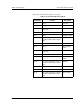
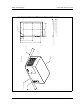
The Luminex 100E analyzer has three electrical and four fluid
connectors that interface to the host system:
• P1 Communications Port
•P2
Synchronization Port
• Power input connector
• Sample Input Tube
• Nonpressurized Sheath Fluid Connector
• Waste Fluid Connector
• Pressurized Sheath Fluid Connector
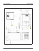
To install the Luminex 100E analyzer into the host system:
1. Connect the USB communications cable from the host system to
the P1 communications port (DB9) on the Luminex 100E
analyzer.
2. Connect the synchronization cable from the host system to the
P2 Synchronization Port (DB15) on the Luminex 100E analyzer.
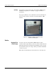
3. Connect the nonpressurized sheath, waste, and pressurized
sheath fluid lines from the host system into the color-coordinated
connectors at the lower left of the sample input tube on the
Luminex 100E analyzer. The connectors snap into the injection
port using firm pressure.
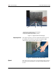
4. Remove the white cap covering the sample input tube and
connect it to the sample aspiration interface from the host
system.
5. Remove the yellow cap covering the power input connector and
connect the power source from within the host system to the
power input connector (21-pin cylindrical connector) on the
Luminex 100E analyzer.
6. Place the Luminex 100E analyzer into the host system.
Note: Due to the weight, use
two people to lift the Luminex
100E analyzer.