
Hardware User Manual Instruction Manual

Luminex 100E User Manual xMAP Technology
3 - 8 PN 89-00002-00-013 Rev. D
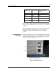
The P1 Communications Port is a nine-pin DB female-style
connector for communication between the P1 port and the host
computing and control system.
Table 1 lists the P1 communications port pinouts.
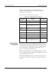
P2 Synchronization
Port (DB15-PIN)
The P2 Synchronization Port is a digital I/O port that provides one
input line and two output lines. The P2 synchronization port is used
to connect the Luminex 100E analyzer and the host computing and
control system. Refer to “P2 Synchronization Port Pinout” on
page 3-9 to see the P2 synchronization port.
The P2 Synchronization Port is a 15-pin DB female style connector
to allow communication between the Luminex 100E analyzer and the
host computing and control system.
The Luminex 100E analyzer uses open collector outputs; the inputs
are designed to interface with open collector outputs from the host
system.
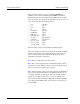
Table 1: P1 Communications Port Pinout
Pin Number voltages Description
Pin 1 None USB D-
Pin 2 Maximum of 5.25 Reserved
Pin 3 No voltage originates from the
Luminex 100E analyzer at this
pin
Reserved
Pin 4 None No connect
Pin 5 None Chassis
ground
Pin 6 Maximum of 5.25 USB D+
Pin 7 None No connect
Pin 8 None USB ground
Pin 9 No voltage originates from the
Luminex 100E analyzer at this
pin
USB Vbus