
Hardware User Manual Instruction Manual

xMAP Technology Luminex 100E Analyzer Overview
PN 89-00002-00-013 Rev. D 3 - 5
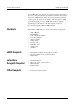
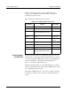
Fluidics • Sheath flow specification rate: 90 µL/second ± 5 µL/second
• Cuvette: 200 micron square flow channel
• Sample injection rate: 1 µL/second ± .05 µL variable default
• Sample uptake volume: 20 - 200 µL
• Pressure connections to the unit should not exceed 10 PSI during
normal operating conditions.
Electronics • Reporter channel detection, A/D resolution: 14 bits
• Communications interface: USB
• Classification and doublet discriminator channel detection:
Avalanche photo diode (APD) with temperature compensation,
A/D resolution: 12 bits
System Overview The Luminex 100E analyzer consists of three subsystems: electronic,
fluidic, and optical. An air filter fits under the front cover of the
analyzer. There is no user access to the optics.
User-Accessible
Components
The following section describes the user-accessible components of
each subsystem, where applicable.
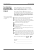
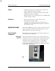
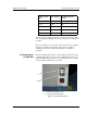
Power Input
Connector
The power input connector receives power when connected to an
external source. The power input connector is shipped with a plastic
cap. Remove the cap to access the 21-pin connector. The 21-pin
cylindrical connector supplies the power for several different
components of the Luminex 100E analyzer, including the fan,
syringe pump, backflush valve, sample valve, analog board, digital
board, red laser, and green laser.
Figure 7. Power Input Connector