
Datasheet


DS064 LUXEON Rebel General Purpose Product Datasheet 20140205 ©2015 Lumileds Holding B.V. All rights reserved. 10
Pad Configuration
Note for Figure 2:
- The Thermal Pad is electrically isolated from the Anode and Cathode contact pads.
Solder Pad Design
Note for Figure 3:
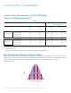
- The photograph below shows the recommended LUXEON Rebel layout on Printed Circuit Board (PCB). This design easily achieves a thermal
resistance of 7K/W.
- Application Brief AB32 provides extensive details for this layout. In addition, the .dwg files are available at www.lumileds.com.
Figure 2. Pad configuration.
Figure 3. Solder pad layout.
3
12
TOP
3
21
BOTTOM
3
THERMAL
2
ANODE
1
CATHODE
PAD
FUNCTION