
Datasheet


LUXEON LED Assembly and Handling Application Brief AB32 20121217 34
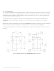
5.8 Void Inspection and Solderability Indicators
An in-line X-Ray machine can inspect for voids after reflow. Philips Lumileds has determined that the two small thermal vias in the thermal pad
footprint minimizes voiding by serving as an air vent during reflow.
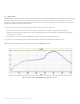
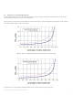
A large percentage of voids in the thermal pad will increase of the thermal resistance. Figure 42 and Figure 43 show the impact of solder voiding on
board thermal resistance (Rθ
c-hs
) based on modeled data.
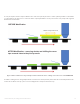
For visual inspection of solder wetting, solderability indicators have been designed in the footprint, see Figure 44.
Figure 42. Impact of voiding in thermal land on thermal resistance for open via design.
Figure 43. Impact of voiding in thermal land on thermal resistance for filled and capped via design.