
Datasheet

LUXEON LED Assembly and Handling Application Brief AB32 20121217 23
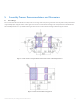
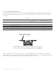
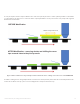
Table 1 summarizes thermal resistance values for typical and high thermal conductivity epoxies. Standard MCPCB design rules yield a board with
10K/W thermal resistance. Increasing the copper thickness and using a thinner dielectric with higher thermal conductivity lowers the thermal
resistance dramatically.
In both cases the copper area extending outside the thermal pad is at least 3mm.
Table 1.
MCPCB Design Parameters
Dielectric Typical epoxy High conductivity epoxy
Dielectric thermal conductivity [W/mK] 0.8 4
Al thickness [mm] 1.5 1.5
Copper thickness [µm] 30 70
Dielectric thickness [µm] 100 85
Total MCPCB thermal resistance 10 5
for low density design [K/W]
The difference between the coefficients of thermal expansion (CTE) of a LUXEON LED and a MCPCB is larger than the difference between the
CTE of a LUXEON LED and an FR4 PCB. Therefore, there is greater stress on the solder joint for a LUXEON LED on MCPCB. Studies by Philips
Lumileds suggest that dielectric epoxy materials have a strong impact on the solder joint reliability. Philips Lumileds, therefore, recommends that
customers contact their MCPCB vendors for suitable dielectric materials.