
Datasheet

LUXEON LED Assembly and Handling Application Brief AB32 20121217 22
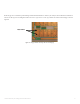
4. MCPCB Board design
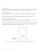
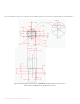
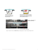
The layout for the MCPCB design is similar to the FR4 layout in Figure 8 but without all the vias, see Figure 29.
In order to minimize thermal resistance the area of copper connected to the thermal pad of a LUXEON LED must be maximized. Philips Lumileds
recommends extending the copper area for the thermal pad 3mm beyond the outline of a LUXEON LED.
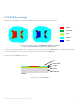
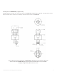
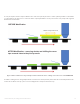
A cross section of the MCPCB is shown below.
Copper
SolderMask
Epoxy
WhiteInk
Solder
Figure 29. Recommended layout for a LUXEON LED on MCPCB. Note that this
layout is similar to the FR4 layout in Figure 8 but without all the vias.
Ink
Solder Mask
Copper
Epoxy
Aluminum
MCPCB
Figure 30. Cross section of MCPCB.