
Datasheet

LUXEON LED Assembly and Handling Application Brief AB32 20121217 17
Impact of the thermal via count
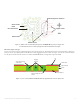
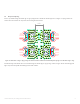
For an open via PTH board, removal of the 14 outer vias increases the thermal resistance by approximately 1K/W. The 14 outer vias are labeled
in Figure 11. Eliminating the two smaller vias in the thermal landing pad increases the Rθ
c-hs
value by 1 K/W as well since the copper area around
the thermal landing pad has a large contribution to the thermal spreading. The optimal copper area extends 3mm beyond the thermal pad. Any
extension beyond 3mm will not significantly lower the thermal resistance. Elimination of both the outer vias and the copper area outside the
thermal pad increases the thermal resistance to above 30 K/W.
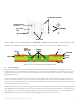
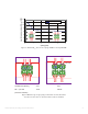
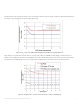
With filled and capped vias, the thermal resistance decreases from 4K/W to 3K/W when adding the additional vias around the 11 vias in the thermal
landing pad as shown in Figure 18.
Effect of component density
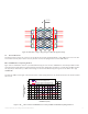
For an open via PTH, bringing the components closer together than 4mm will lead to elimination of vias and decreases the copper area around the
thermal pad. If the spacing is less than 2mm, the thermal resistance will increase dramatically. Figure 21 shows the simulated thermal resistance as a
function of spacing. Figure 22 shows the reduction of vias when the spacing decreases from 4mm to 2mm. These simulation results correspond to a
0.8mm FR4 board thickness with 70µm of total copper plating and 35µm copper plating via.
0
1
2
3
4
5
6
01020304
05
0
# of vias per LUXEON LED
Rth
c-hs
(K/W)
Figure 20. Simulation of the thermal resistance as a function of number of vias (filled and capped via).