LUXEON Rebel General Purpose White Portfolio High flux and color stability Technical Datasheet DS64 LUXEON® Rebel General Purpose White Portfolio Introduction The LUXEON® Rebel General Purpose White Portfolio LEDs in this datasheet are ideal for all lighting and illumination applications. These flux differentiated parts, like all other LUXEON Rebel LEDs, provide the industry’s best lumen maintenance, superior reliability and quality white light that make them the most widely used power LEDs today.
Table of Contents Product Nomenclature ................................................................................................................................................ 3 Average Lumen Maintenance Characteristics ........................................................................................................ 3 Environmental Compliance .........................................................................................................................................
Product Nomenclature LUXEON Rebel is tested and binned at 350 mA.
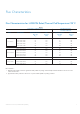
Flux Characteristics Flux Characteristics for LUXEON Rebel, Thermal Pad Temperature=25°C Table 1.
Flux Characteristics, Continued Flux Performance, Binning, and Supportability Volume LEDs are produced with semiconductor technology that is subject to process variation, yielding a range of flux performance that is approximately Gaussian in nature. In order to provide customers with fine granularity within the overall flux distribution, Philips Lumileds separates LEDs into fixed, easy to design with, minimum luminous flux bins.
Optical Characteristics Lambertian LUXEON Rebel at Test Current [1] Thermal Pad Temperature = 25°C Table 2. Color Cool-White Neutral-White Warm-White Color Temperature [3] [4] CCT Min. Typ. Max. 4500K 3500K 2540K 6500K 4100K 3100K 10,000K 4500K 3500K Typical Total Included Angle [5] (degrees) !0.90V Typical Viewing Angle [6] (degrees) 2! 1/2 160 160 160 120 120 120 Notes for Table 2: 1. Test current is 350 mA for all LXML-Pxx1-0xxx products. 2. CCT ±5% tester tolerance. 3.
Electrical Characteristics Electrical Characteristics at 350 mA for LUXEON Rebel, Part Numbers LXML-Pxx1-0xxx, Thermal Pad Temperature = 25ºC Table 3. Color Min. Forward Voltage Vf [1] (V) Typ. Typical Temperature Coefficient of Forward Voltage [2] (mV/°C) "Vf / "TJ Max. Typical Thermal Resistance Junction to Thermal Pad (°C/W) R! J-C Cool-White 2.55 3.15 3.99 -2.0 to -4.0 10 Neutral-White Warm-White 2.55 2.55 3.15 3.15 3.99 3.99 -2.0 to -4.0 -2.0 to -4.0 10 10 Notes for Table 3: 1.
Absolute Maximum Ratings Table 5.
Reflow Soldering Characteristics JEDEC 020c Table 7.
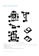
Mechanical Dimensions Figure 1. Package outline drawing. Notes for Figure 1: 1. Do not handle the device by the lens—care must be taken to avoid damage to the lens or the interior of the device that can be damaged by excessive force to the lens. 2. Drawings not to scale. 3. All dimensions are in millimeters. 4. The Thermal Pad is electrically isolated from the Anode and Cathode contact pads.
Pad Configuration Figure 2. Pad configuration. Note for Figure 2: 1. The Thermal Pad is electrically isolated from the Anode and Cathode contact pads. Solder Pad Design Note for Figure 3: The photograph below shows the recommended LUXEON Rebel layout on Printed Circuit Board (PCB). This design easily achieves a thermal resistance of 7K/W. Application Brief AB32 provides extensive details for this layout. In addition, the .dwg files are available upon request. Figure 3. Solder pad layout.
Wavelength Characteristics Cool-White at Test Current Thermal Pad Temperature = 25°C Relative ve Spectral Power Distribution 1 0.8 0.6 0.4 0 2 0.2 0 350 400 450 500 550 600 650 700 750 800 Wavelength (nm) Figure 4a. Cool-white color spectrum of typical CCT part, integrated measurement Neutral-White at Test Current Thermal Pad Temperature = 25ºC Relative ve Spectral Power Distribution 1 0.8 0.6 0.4 0.2 0 350 400 450 500 550 600 650 700 750 800 Wavelength (nm) Figure 4b.
Wavelength Characteristics, Continued Warm-White at Test Current Thermal Pad Temperature = 25ºC Relative ve Spectral Power Distribution 1 0.8 0.6 0.4 0.2 0 2 0 350 400 450 500 550 600 650 700 750 800 Wavelength (nm) Figure 4c. Warm-white color spectrum of typical CCT part, integrated measurement.
Typical Light Output Characteristics over Temperature Cool-White, Neutral-White, and Warm-White at Test Current 1.2 Normalized alized Luminous Flux ux 1.1 1.0 0.9 0.8 0.7 0.6 0.5 -20 0 20 40 60 80 100 120 140 Thermal Pad Temperature (°C) Figure 5. Relative luminous flux vs. thermal pad temperature.
Typical Forward Current Characteristics Cool-White, Neutral-White and Warm-White Thermal Pad Temperature = 25ºC 1200 Forward Current (mA) 1000 800 600 400 200 0 2.8 2.9 3 3.1 3.2 3.3 3.4 3.5 3.6 Forward Voltage (V) Figure 6. Forward current vs. forward voltage.
Typical Relative Luminous Flux Typical Relative Luminous Flux vs. Forward Current for Cool-White, Neutral-White and Warm-White Thermal Pad Temperature = 25°C 2.50 Normalized Luminous Flux 2.25 2.00 1.75 1.50 1.25 1.00 0.75 0.50 0.25 0.00 0 200 400 600 800 1000 1200 Forward Current (mA) Figure 7. Relative luminous flux or radiometric power vs. forward current for cool-white, neutral-white and warm-white Thermal Pad = 25ºC maintained, test current 350 mA.
Current Derating Curves Current Derating Curve for 350 mA Drive Current Cool-White, Neutral-White and Warm-White 400 IF - Forward Current (mA) 350 300 250 15°C/W 200 25°C/W 150 35°C/W 100 45°C/W 50 0 0 25 50 75 100 125 150 175 TA - Ambient Temperature (°C) Figure 8. Maximum forward current vs. ambient temperature, based on TJMAX = 150ºC.
Current Derating Curves, Continued Current Derating Curve for 1000 mA Drive Current Cool-White, Neutral-White and Warm-White 1200 IF - Forward Current (mA) A) 1000 800 600 15°C/W 400 25°C/W 200 0 0 25 50 75 100 125 150 175 TA - Ambient Temperature (°C) Figure 10. Maximum forward current vs. ambient temperature, based on TJMAX = 150ºC.
Typical Radiation Patterns Relative Intensity (%) Typical Spatial Radiation Pattern for Cool-White, Neutral-White and Warm-White Lambertian Angular Displacement (deg) Figure 11a. Typical representative spatial radiation pattern for cool-white, neutral-white and warm-white lambertian. Typical Polar Radiation Pattern for White Lambertain 0º - 30º 30º - 60º 60º - 90º 0 20% 40% 60% 80% 90º 100% Figure 11b. Typical polar radiation pattern for cool-white, neutral-white and warm-white lambertian.
Typical Radiation Patterns, Continued ∆x Typical Color Coordinates vs. Angle for Warm-White Angular Displacement in Degrees ∆y Figure 12a. X coordinate vs. angle for warm-white LUXEON Rebel. Angular Displacement in Degrees Figure 12b. Y coordinate vs. angle for warm-white LUXEON Rebel.
Emitter Pocket Tape Packaging Figure 13.
Emitter Reel Packaging Figure 14.
Product Binning and Labeling Purpose of Product Binning In the manufacturing of semiconductor products, there is a variation of performance around the average values given in the technical data sheets. For this reason, Philips Lumileds bins the LED components for luminous flux, color and forward voltage (Vf ). Decoding Product Bin Labeling LUXEON Rebel Emitters are labeled using a three or four digit alphanumeric code (CAT code) depicting the bin values for emitters packaged on a single reel.
Luminous Flux Bins Table 8 lists the standard photometric luminous flux bins for LUXEON Rebel emitters (tested and binned at 350 mA). Although several bins are outlined, product availability in a particular bin varies by production run and by product performance. Not all bins are available in all colors. Table 8.
Cool-White Bin Structure Figure 15. Cool-White bin structure.
Cool-White LUXEON Rebel Emitters are tested and binned by x,y coordinates. 19 Color Bins, CCT Range 10,000K to 4,500K. Table 9. Cool-White Bin Coordinates Bin Code Y0 YA XM XN X0 XP WM WN W0 WP X Y 0.274238 0.303051 0.307553 0.282968 0.282968 0.307553 0.311163 0.289922 0.301093 0.313617 0.314792 0.303051 0.303051 0.314792 0.316042 0.305170 0.305170 0.316042 0.317466 0.307553 0.307553 0.317466 0.319597 0.311163 0.313617 0.328636 0.328823 0.314792 0.314792 0.328823 0.329006 0.316042 0.316042 0.
Neutral-White Bin Structure Neutral-White LUXEON Rebel Emitters are tested and binned by x,y coordinates. 12 Color Bins, CCT Range 4,500K to 3,500K. Figure 16. Neutral-White bin structure. Table 10. Neutral-White Bin Coordinates Bin Code TM TN T0 TP SM SN X Y 0.367294 0.385953 0.381106 0.364212 0.364212 0.381106 0.378264 0.362219 0.362219 0.378264 0.374075 0.359401 0.359401 0.374075 0.370582 0.357079 0.385953 0.402270 0.396279 0.381106 0.381106 0.396279 0.392368 0.378264 0.400290 0.412995 0.
Warm-White Bin Structure Warm-White LUXEON Rebel Emitters are tested and binned by x,y coordinates. 15 Color Bins, CCT Range 3,500K to 2,540K. Figure 17. Warm-White bin structure.
Table 11. Warm-White Bin Coordinates Bin Code QN QO QP PN PO PP NN NO X Y 0.414776 0.431186 0.423956 0.408593 0.408593 0.423956 0.416487 0.402113 0.402113 0.416487 0.409996 0.396564 0.431186 0.445639 0.437578 0.423956 0.423956 0.437578 0.429373 0.416487 0.416487 0.429373 0.422124 0.409996 0.445639 0.461404 0.452512 0.437578 0.437578 0.452512 0.443600 0.429373 0.416097 0.423386 0.406472 0.399525 0.399525 0.406472 0.389001 0.382156 0.382156 0.389001 0.373814 0.367284 0.423386 0.428680 0.411632 0.
Forward Voltage Bins Table 13 lists minimum and maximum Vf bin values per emitter. Although several bins are outlined, product availability in a particular bin varies by production run and by product performance. Table 12. Vf Bins Bin Code Minimum Forward Voltage (V) Maximum Forward Voltage (V) B C D E F G 2.55 2.79 3.03 3.27 3.51 3.75 2.79 3.03 3.27 3.51 3.75 3.
Company Information Philips Lumileds is the world’s leading provider of power LEDs for everyday lighting applications. The company’s records for light output, effi cacy and thermal management are direct results of the ongoing commitment to advancing solid-state lighting technology and enabling lighting solutions that are more environmentally friendly, help reduce CO2 emissions and reduce the need for power plant expansion.