
Installation Guide

20W
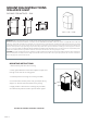
WALLPACK LIGHT
5.50’’ x 7.90’’ x 13.00’’
MOUNTING INSTRUCTIONS
SUITABLE FOR WATTAGE:
D
E
F
C
1
2
3
4
B
A
3
2
1
5
C
D
4
6
7
8
A
B
SHEET 1 OF 1
SCALE:
TITLE:
MATERIAL:
DATE
SIGNATURE
NAME
DEBUR AND
BREAK SHARP
EDGES
FINISH:
UNLESS OTHERWISE SPECIFIED:
DIMENSIONS ARE IN MILLIMETERS
SURFACE FINISH:
TOLERANCES:
LINEAR:
ANGULAR:
Q.A
MFG
APPV'D
CHK'D
DRAWN
WEIGHT:
VER01.16
FIXTURE IS SUITABLE FOR WET LOCATION
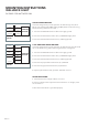
MOUNTING INSTRUCTIONS:
1. Remove back plate from front housing
2. Place gasket between wall and back plate and pull wires
through center hole of mounting plate
3. Fix back plate to wall using two screws (provided)
4. Connect xture leads to power and ground (see wiring
diagram on back for standard and dimming wiring)
5. Apply outdoor rated silicone caulking (not provided)
around the back plate and wall to prevent water ingress
CAUTION: For proper weatherproof function all gaskets must be seated properly and all screws inserted and tightened rmly. Apply weatherproof
silicone sealant (NOT included) around the edge of the Wall Box and/or Junction Box. This is especially important with an uneven wall surface.
Silicone all plugs and unused conduit entries.
IMPORTANT: READ BEFORE REMOVING FIXTURE FROM CARTON. RETAIN FOR FUTURE REFERENCE.
This xture must be wired and installed in accordance with the NATIONAL ELECTRIAL CODE and all state and applicable local codes and
ordinances. These codes and ordinances supersede any and all instruction contained herein. Installation should be performed only by a licensed
and bonded electrician and a person familiar with the construction and operation of the product and the hazards involved in the installation and
operation of this product. Proper grounding is required for safety. Make certain power is OFF before installing or maintaining xture. Failure to
do so may increase the RISK OF PERSONAL INJURY, PROPERTY DAMAGE, FIRE, AND DEATH. The manufacturer takes no responsibility for the
product not installed under those guidelines and those contained in this document. See wiring diagram on back
7.90 in
200 mm
5.50 in
139 mm
13.00 in
330 mm
13.00 in
330 mm
5.50 in
139 mm
7.90 in
200 mm