
Product Manual


2
GF6570B-1-INS-LAB-RevD10
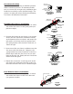
stabilizer
rail guide
head end slot
anti-slide tab
spring button
long end
detail: install
head end
crossbrace
head end
spring
button
rail guide
head end
crossbrace
detail: head end
crossbrace
installed
head end
foot deck
angle
locate
foot end
slots
head end
foot end slot
detail area
foot end
Crossbrace Position
Please note that crossbrace installation position
differs from nal position. To facilitate installa-
tion, it is necessary to expose the stabilizers that
hook the crossbraces to the bed deck angle. The
pictures at right will aid you during the following
crossbrace installation instructions.
Head End Crossbrace Installation
1. Locate the two head deck angle slots on either
side of the bed closest to the pivot point (see
picture at right).
2. Position the head end crossbrace so it extends
across the bed. Ensure the stabilizers remain
at the bottom of the crossbrace and rotate the
rail guides so the long ends face upward and
the spring buttons face the bed's head end, as
shown at right.
3. Insert one of the crossbrace stabilizers into the
slot across the bed from you. Compress the
spring-loaded crossbrace until the second sta-
bilizer aligns with the slot closest to you and
lower it into the slot. Slowly release crossbrace
until it locks into place.
4. Rotate the crossbrace so the long ends of the
rail guides face downward and the spring but-
tons face the bed's foot end, as shown at right.
Foot End Crossbrace Installation
1. Locate the two foot deck angle slots on either
side of the bed closest to the bed's foot end
(see picture at right).
head end
pivot point
head end slot
head deck
angle
foot end
locate
head end
slots
head end
detail area
bed deck angle
stabilizer
spring button
anti-slide tab
rail guide
crossbrace
in installation
position
crossbrace
rotated
to final
position