MODEL US0208 / US0208PL SEMI-ELECTRIC BED MODEL US0458 / US0458PL FULL-ELECTRIC / LOW BED USER MANUAL READ THIS MANUAL BEFORE OPERATING THE PATRIOT HOMECARE BED. SAVE THIS MANUAL FOR FUTURE USE. NOTE: THE MOST CURRENT VERSION OF THIS MANUAL CAN BE FOUND ONLINE AT www.grahamfield.
CONTENTS 1 SAFETY................................................................................................................................................................................................ 3 WARNING / CAUTION SUMMARY............................................................................................................................................... 3 2 INTRODUCTION, PATRIOT™ HOMECARE BED USER MANUAL.............................................................................
1 SAFETY The safety statements presented in this chapter refer to the basic safety information that the operator of the Patriot™ Homecare Bed shall pay attention to and abide by. There are additional safety statements in other chapters or sections, which may be the same as or similar to the following, or specific to the operations.
2 INTRODUCTION, PATRIOT™ HOMECARE BED USER MANUAL This manual contains assembly and maintenance instructions for your Model US0208 / US0208PL Semi-Electric and US0458 / US0458PL Full-Electric / Low Patriot™ bed. Read the entire manual carefully before using your bed, and refer to it during use if you have questions. THERMAL MOTOR PROTECTION This product is powered by a quiet, efficient DC motor system.
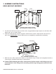
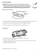
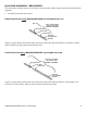
3 ASSEMBLY INSTRUCTIONS HEAD AND FOOT ASSEMBLY hook rivet motor cam foot section hook head section rivet Assembly, head and foot sections Note: Grid deck not shown for clarity 1. Lay the head and foot sections on their sides at approximately right angles to each other with motor cams up, as shown above. 2. Slide the head and foot sections together until the foot section's hook catches the head section’s rivet on both sides. Ensure both rivets are completely seated before continuing.
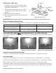
MOTOR ASSEMBLY WARNING: Assemble motor on bed as follows. While it is possible to install the motor backwards, avoid it! Incorrect installation could cause the bed to move in unexpected ways. Note that the motor ends are labeled and embossed with head and foot symbols (shown at right). Ensure that bed head and motor head, and bed foot and motor foot, are matched. Head Foot Remove motor slide caps slide cap motor Remove motor slide caps 1.
Install motor slide caps 7. Position the caps as shown at right so that the grooves in the slide cap are aligned with the grooves in the motor. 8. Apply straight downward pressure to each end of the cap while sliding into the closed position. 9. Repeat step 8 for the other cap. 10. Ensure that all four corners of each slide cap are engaged. pressure slide cap motor Install motor slide caps WARNING: Ensure that the motor is assembled on bed as instructed above before use.
BED END ASSEMBLY Full-electric bed only (US0458/US0458PL): Lock motor spring coupling SLIDE IN AND ROTATE TO LOCK ROTATE TO UNLOCK coupler Unlocking coupler coupler Locking coupler gearbox gearbox Before attaching foot end, ensure that hi/lo motor spring coupling is retracted and locked to avoid interference with end gearbox shaft as shown at above right. All bed models: Assemble bed ends 1. Insert one locking and one non-locking caster into each bed end.
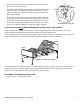
7. After bed ends have been attached, install bed end safety pins to act as safety latches. (Bed End Safety Pin Kit part number: 690-1000-100; includes four clevis pins, four hitch pins and four washers). A lanyard is supplied to attach hardware to the bed or the end upon disassembly. washer bed end hook Insert pins and washer as shown at right, with flat washer on outside of bed end hook.
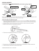
HI/LO ROD ASSEMBLY / BED LENGTH The hi/lo rod assembly consists of an inner and outer tube with a spring button lock to keep them together. 1. Assemble outer and inner tubes: Semi-electric bed only (US0208/US0208PL): Assemble hi/lo rod spring button Hi/lo rod assembly semi-electric bed US0208 / US0208PL inner tube outer tube inserted spring button position Depress spring button and insert inner tube into outer tube until third hole is reached as shown above. Release spring button to lock it into hole.
All models: Attach HI/LO rod to gearbox or motor shaft pins gearbox shaft (or motor shaft) pin hi/lo rod slot Attach hi/lo rod to gearbox or motor shaft Both ends of the hi/lo rod assembly have a slot to mount on the foot end motor shaft pins and bed end gearbox shaft pins as shown above. Follow steps 2-3 to mount the hi/lo rod assembly on the gearboxes.
4 BED OPERATION WARNING: Ensure that bed is secure and assembled as instructed on previous pages before operating. Note: In the event of a power failure, use a standard 9V battery to lower the bed's head and foot sections (the 9V battery connection is attached to the motor). When used with the battery, the motor will only lower, not lift, the head and/or foot sections.
CRANK OPERATION: SEMI-ELECTRIC BED ONLY (US0208/US0208PL) Use the crank at the center foot of the semielectric bed (shown at right) to change bed height (raise or lower entire deck). foot crank Crank operation TRENDELENBURG POSITION, ALL MODELS (HEAD END AT LOWER ELEVATION THAN FOOT END) 1. Lower bed to its lowest height. Disengage the hi/lo rod by compressing the spring button and removing the hi/lo rod from the motor or bed end. 2.
5 SPECIFICATIONS, ALL MODELS * * Specifications are subject to change without notice. Deck height High position Deck height: High Position US0208/US0208PL: 24.0 inches US0458/US0458PL with casters in low position: 20.0 inches US0458/US0458PL with casters in standard position: 23.5 inches Low position Deck height: Low Position US0208/US0208PL: 15.0 inches Bed length US0458/US0458PL with casters in low position: 9.
6 ACCESSORIES: BED RAILS Patriot™ Homecare Bed decks are equipped with patent-pending slots specifically for bed rail installation, providing a fixed place to mount GF bed rails. Two styles of Lumex® bed rails are described in Section 6: 1) The Patriot™ Liberty bed rail system, designed specifically for Patriot™ Beds, and 2) Standard Lumex® bed rails Please read the following bed rail safety information.
GF6590B-1: Half No-Gap Head Rail The Half No-Gap Head Rail, which provides a full head coverage of 31.5 inches, extends to eliminate the gap between the head board and the end of the rail. The GF6590B-1 mounted on the bed's head and the GF6580B-1 mounted on the bed's foot combine to create the Patriot™ split rail system. GF6590B-1 Half No-Gap Head Rail GF6570B-1: Full Length Rail The Full Length rail is a nominal, telescoping full length rail that provides maximum length rail perimeter coverage.
HEADBOARD FOOTBOARD LX5088: No-Gap Bed Rail LX5088 No Gap Side Rail B G2 Spring Buttons G3 B Position spring-loaded crossbraces #B into slots G2 and G3 on both sides of bed with spring buttons facing inward as shown above. GF6580A-1: Low Universal Half Rail Cable tie GF6580A-1 Low Universal Half Rail Secure crossbrace to head deck angle with cable tie HEADBOARD B SUGGESTED RAIL TO HEADBOARD MINIMUM OF 9.25" Follow same procedure for mounting half rails on foot-end using G3 slots.
7 SERVICE PARTS, ALL MODELS Service parts for all bed models are shown below and on the following two pages. See pictures and tables for appropriate service parts. Note: To order service parts, contact our Customer Service department at 800-365-2338 (fax 920-929-8213).
BED END COMPONENTS HEAD 5 6 FOOT 8 2 7 Item Part number 1 2 3 4 5 690-7001-901 690-7601-901 690-7004-901 690-7604-901 690-7001-902 690-7601-902 690-7004-902 690-7604-902 999-0301-904 100-6330-014 100-6330-015 100-4200-012 554-2001-015 690-5001-025 690-5004-015 690-5004-025 6 7 8 9 554-2001-059 690-5004-059 600-2001-912 600-2001-916 999-0353-000 600-2001-910 690-1000-100 3 4 Description Head bed end, semi-electric, walnut panels Head bed end, semi-electric, plastic panels Head bed end, full-elect
BED SERVICE PARTS HEAD FOOT 1 4 2 3 Item Part number 1 2 3 4 5 690-2001-913 690-2001-411 690-2001-410 690-3001-943 690-2001-414 690-3001-415 690-7001-944 690-3001-941 554-2018-901 690-2001-412 690-1000-100 Description Motor and pendant, semi-electric Pendant, semi-electric Motor, semi-electric Motor and pendant, full-electric Pendant, full-electric Motor, full-electric Motor and bracket, hi/lo Motor, hi/lo, full-electric Hi/lo rod assembly Motor slide covers End locking hardware and lanyard, set of 4
8 MAINTENANCE AND SAFETY CHECKS Perform the following as needed or between patient placements, whichever happens sooner: Electronics and Motors Bed frames and sleeping surface Cleaning Lubrication and mechanical Check all controls to ensure that all functions work properly. Foot control Head control Hi/Lo (if applicable) Check all cables for damaged or frayed wires. Power cord Pendant hand control cord Check to ensure that all plugs are fully inserted or attached.
9 WARRANTY GF Health Products, Inc. warrants the Patriot™ US0208 / US0208PL Semi-Electric Homecare Bed Patriot™ US0458 / US0458PL Full-Electric / Low Bed as follows: ● Two year warranty for defects in workmanship and materials of mechanical components, frame, and electronics. ● During the warranty period, defective items will be repaired or replaced at manufacturer's option.
10 INDEX A Assembly instructions 5 B Bed end assembly 8 Bed end safety pins, install 9 Bed extension kit, 84" 14 Bed height, low, full-electric 7 Bed height, standard, full-electric 7 Bed length adjustment 10 Bed operation 12 Bed rails 15 Bed rail safety 15 C Caster position (full-electric bed only) 7 Caution statement, significance 3,?5 Crank operation (semi-electric bed only) 13 D Deck height (high position) 14 Deck height (low position) 14 P Pendant hand control operation, full-electric 12 Pendant han
U.S.A. Corporate Headquarters: GF Health Products, Inc. 2935 Northeast Parkway Atlanta, Georgia 30360 telephone: 800-347-5678, 770-447-1609 fax: 800-726-0601, 678-291-3232 www.grahamfield.