
Datasheet


LUMEL S.A., ul. Słubicka 1, 65-127 Zielona Góra, Poland / tel.: +48 68 45 75 139, fax: +48 68 32 54 091 / e-mail:export@lumel.com.pl /
www.lumel.com.pl
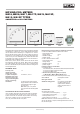
Fig. 4. External dimensions of MB16 meters
Fig. 5. Fixing of meters in the panel
FASTENING ON PANELS
MA16 meters
The meters are adapted to be mounted from the front of panels and
then they are equiped with two spring holders, which can be fixed on
arbitrary opposite case sides (Fig. 1b) or to be mounted from the rear
of panels and then they are equiped with two screw holders which can
be fixed on arbitrary, opposite case corners (Fig. 1a).
MA17, MA19 and MA12 meters
In their basic execution these meters are adapted to be mounted from
the rear of panels by means of two screw holders which can be fixed
on arbitrary opposite case corners (Fig. 5).
Execution of meters with IP 65
The meter is fixed in the panel by means of 4 screw holders.
After agreeing with the manufacturer, MA17 and MA19 meters can be
delivered with a snap fastened frontal frame and then these meters can
be mounted from the front of panels by means of two spring holders
fixed on arbitrary opposite case sides.
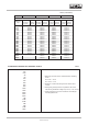
CODING OF THE WORKING POSITION
Code Working position
O c3, a = 90°
A c1, a = 0°
B c2, a = 15°
C c2, a = 30°
D c2, a = 45°
E c2, a = 60°
F c2, a = 75°
H c4, a = 105°
I c4, a = 120°
Table 4
ORDERING PROCEDURE
In the order one must specify: name and type of meter, measuring range,
shunt data if the meter is foressen to co-operate with an interchange-
able shunt, working position, kind of climat (only for tropical versions),
kind of holders and eventual additional requirements. One must order
interchangeable shunts or D2 series resistors. When ordering meters
for measuring a.c. current or a.c. voltage, one must add to the meter
name „rectifier” - (rectifier meter)
Example of order:
MA16 ammeter, 40 A, c2 30, TIII, screw holders, 0…40 A range
IP54, B2/60 mV- 40 A shunt, IP65.
MA16 – moving-coil meter (48 x 48 mm),
40 A – 40 A range,
c2 30 – working position 30° with relation to horizontal position
(table 5),
TIII – design and materials adapted to specific tropical klimat,
Screw holders – type of holders (screw or spring-holders),
0…40 A – measuring range on the dial,
B2/60 mV/ 40 A – to co-operate with a 40 A shunt of B2 type
IP 54 – protection grade of the casting front
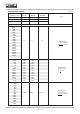
Code Working position
A c3, a = 90°
B c1, a = 0°
C c2, a = 15°
D c2, a = 30°
E c2, a = 45°
F c2, a = 60°
G c2, a = 75°
H c4, a = 105°
I c4, a = 120°
Table 5
(only for MA16)