
User Manual


Document: 66APPMAN Rev: H 6 of 32
Table 8
TRINITY Analog Model Options
Model #
# of
Channels
Drive
Current
Output Voltage
Range (under
load Conditions)
Maximum # of
LEDs per
Channel
(typical)
66-12-0600-ANA-3 12 600 mA 6 to 27 Vdc 2 to 8
66-12-0700-ANA-3 12 700 mA 6 to 27 Vdc 2 to 8
66-09-0800-ANA-3 9 800 mA 6 to 27 Vdc 2 to 8
66-09-0900-ANA-3 9 900 mA 6 to 27 Vdc 2 to 8
66-09-1000-ANA-3 9 1000 mA 6 to 27 Vdc 2 to 8
66-06-1200-ANA-3 6 1200 mA 6 to 27 Vdc 2 to 8
66-06-1400-ANA-3 6 1400 mA 6 to 27 Vdc 2 to 8
70-12-0300-ANA-3 12 300 mA 12 to 47 Vdc 4 to 12
70-12-0350-ANA-3 12 350 mA 12 to 47 Vdc 4 to 12
70-09-0400-ANA-3 9 400 mA 12 to 47 Vdc 4 to 12
70-09-0500-ANA-3 9 500mA 12 to 47 Vdc 4 to 12
70-06-0600-ANA-3 6 600 mA 12 to 47 Vdc 4 to 12
70-06-0700-ANA-3 6 700mA 12 to 47 Vdc 4 to 12
Table 9
Analog Interface Specifications
Control Method
Analog 0-10Vdc
IEC 60929 Annex E out-
puts 0.5mA maximum or
variable
0-10VDC voltage source;
class 2 outputs
Master, Zone1 Zone2, Zone3,
Zone4 outputs each source 0.5mA
maximum
Loss of Analog
Input Signal
Outputs will go to 100% light intensity in less than 1 second
Connection Method
UL recognized cage clamp connector
12 AWG to 28 AWG wiring
Electrical Isolation
Master, Zone 1, Zone 2, Zone 3, Zone 4 outputs
electrically isolated from earth ground
Document: 66APPMAN Rev: H 27 of 32
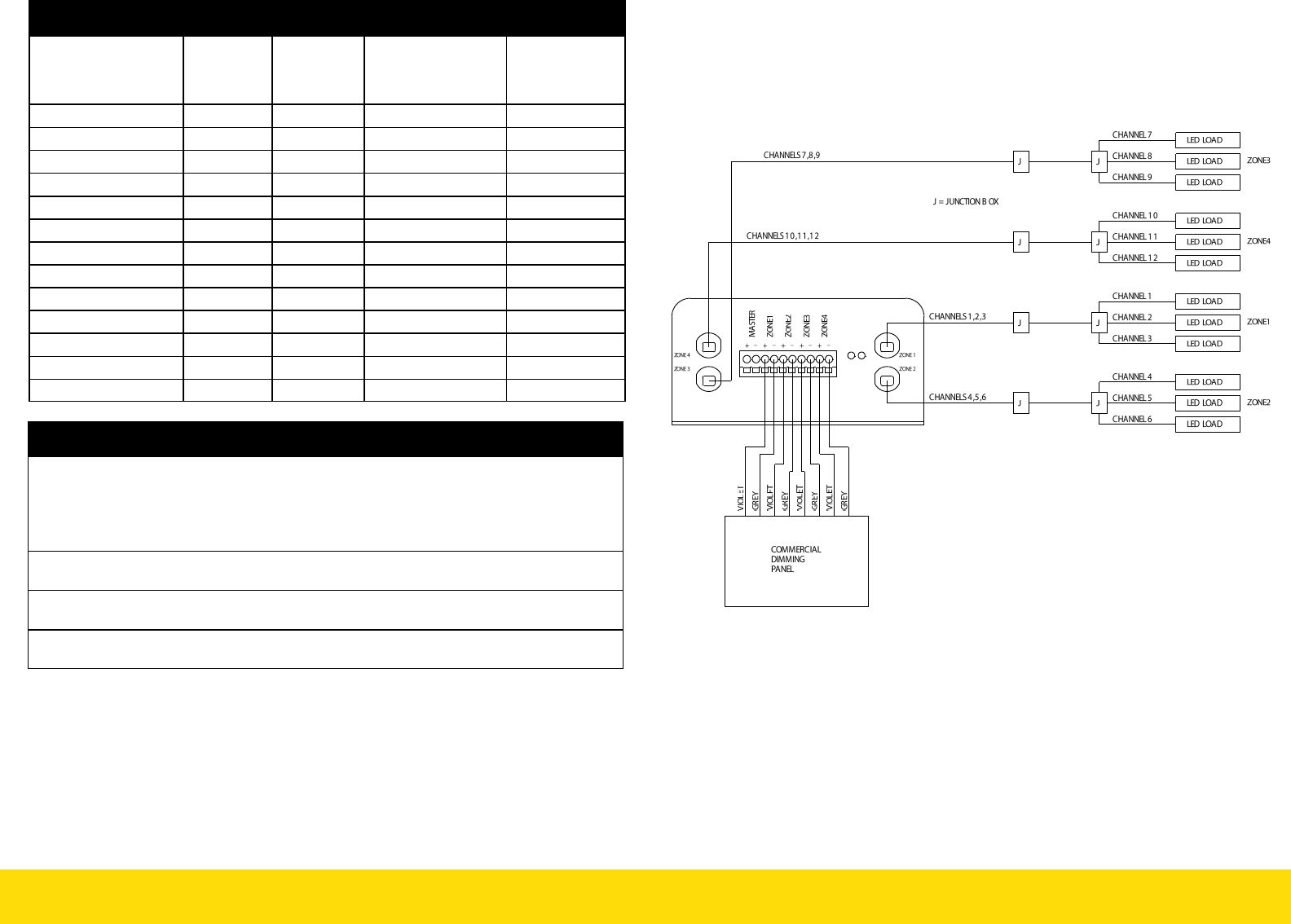
(1)TRINITY ANALOG, (1) COMMERCIAL DIMMING PANEL WITH
(4) 0-10VDC ANALOG CONTROL SIGNALS
Note: This wiring configuration provides independent dimming control
for each zone 1,2,3,4 with a commercial dimming interface comprising (4)
0-10Vdc control signals.