
User Manual


Document: 66APPMAN Rev: H 14 of 32
9.0 DIMMING CONTROL OPTIONS
Trinity LED Driver Dimmer is available with either DMX or 0-10V analog
control dimming options.
DMX control configurations follow the ESTA DMX-512A standard.
Specifications can be found in table 7 at the beginning of this manual.
Trinity LED Driver Dimmer DMX Installation information, typical wiring
diagrams etc. are found in section 10 of this manual.
Analog 0-10V control configurations follow both the IEC 60929 (AnnexE)
and ESTA E1.3-2001 standards. Specifications can be found in table 9 at
the beginning of this manual.
Trinity LED Driver Dimmer Analog installation information, typical wir-
ing diagrams etc. may be found in section 11 of this manual.
Trinity PC Multi-Zone Analog installation information may be found in
section 12 of this manual.
Document: 66APPMAN Rev: H 19 of 32
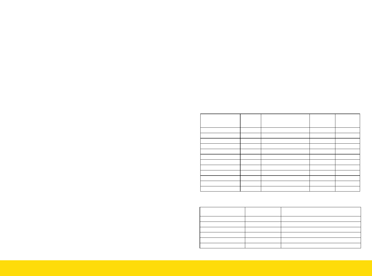
10.6 Output Channel Connections and DMX Address Mapping
DMX Address
Output
Channel
Belden/Alpha or
Equivalent Wire Color/
Polarity
Fixture #
Fixture LED
Color
Base Address (BA) 1
WHT + / BLK - 1
Blue
BA +1 2
RED + / BLK - 1
Red
BA+2 3
GREEN + / BLK - 1
Green
BA+3 4
WHT + / BLK - 2
Blue
BA+4 5
RED + / BLK - 2
Red
BA+5 6
GREEN + / BLK - 2
Green
BA+6 7
WHT + / BLK - 3
Blue
BA+7 8
RED + / BLK - 3
Red
BA+8 9
GREEN + / BLK - 3
Green
BA+9 10
WHT + / BLK - 4
Blue
BA +10 11
RED + / BLK - 4
Red
BA +11 12
GREEN + / BLK - 4
Green
The 3 position rotary switches sets the DMX address of the
TRINITY LED Driver Dimmer.
IMPORTANT: Each channel within the TRINITY DMX requires a DMX
address. The rotary switch address identifies the Base
Address (BA), which is output channel ‘1’. Output channel 2 will be
the next address (BA+1) and so on up to output channel 12 (BA + 11).
The TRINITY DMX will automatically detect a change in address in
less than 2 seconds. No recycling of the AC input is required to im-
plement a change in address location.
In the case of daisy chained TRINITY DMX units, only the last
unit in the chain is terminated by means of a 120 ohm +5%/-10%
impedance inserted into the DMX connector.
DMX Address Output Channel
Belden/Alpha or Equivalent Wire Color/
Polarity
Base Address (BA) 1
WHT + / GREEN -
BA + 1 2
RED + / BLK -
BA + 2 3
WHT + / GREEN -
BA + 3 4
RED + / BLK -
BA + 4 5
WHT + / GREEN -
BA + 5 6
RED + / BLK -
6 Channel Units
12 & 9 Channel Units