
User Manual


Document: 66APPMAN Rev: H 20 of 32
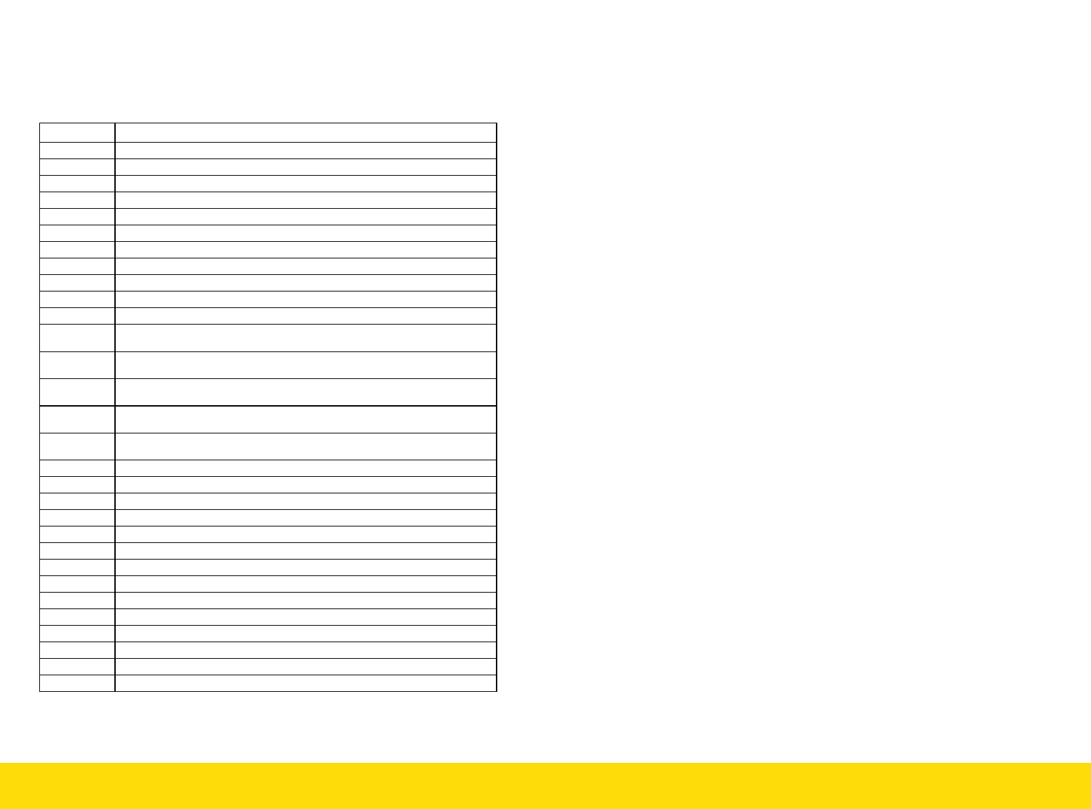
10.7 STANDALONE TEST MODES
Test modes are specified by address location and may be used to
debug network connections or provide standalone color changing
options without the need for a DMX controller. Colors are assuming
LED loads are connected in RGB configuration as shown in section 9.4)
ADDRESS FUNCTION/SEQUENCE
000 NO FUNCTION
001-512 DMX ADDRESS MODE
513 GREEN ON
514 RED ON
515 BLUE ON
516 BLUE & RED ON (MAGENTA)
517 BLUE & GREEN ON (CYAN)
518 GREEN & RED ON (YELLOW)
519 ALL OUTPUTS AT 5%
520 EACH COLOR RAMPING UP AND DOWN INDIVIDUALLY – SPEED 1
521 EACH COLOR RAMPING UP AND DOWN INDIVIDUALLY – SPEED 2
522 CROSS FADE BETWEEN COLOURS (RED UP, GREEN UP, RED
DOWN, BLUE UP ETC.) – SPEED 1
523 CROSS FADE BETWEEN COLOURS (RED UP, GREEN UP, RED
DOWN, BLUE UP ETC.) – SPEED 2
524 CROSS FADE BETWEEN COLOURS (RED UP, GREEN UP, RED
DOWN, BLUE UP ETC.) – SPEED 3
525 CROSS FADE BETWEEN COLOURS (RED UP, GREEN UP, RED
DOWN, BLUE UP ETC.) – SPEED 4
526 CROSS FADE BETWEEN COLOURS (RED UP, GREEN UP, RED
DOWN, BLUE UP ETC.) – SPEED 5
530 ALL ON
531 CHANNEL 1 ON
532 CHANNEL 2 ON
533 CHANNEL 3 ON
534 CHANNEL 4 ON
535 CHANNEL 5 ON
536 CHANNEL 6 ON
537 CHANNEL 7 ON
538 CHANNEL 8 ON
539 CHANNEL 9 ON
540 CHANNEL 10 ON
541 CHANNEL 11 ON
542 CHANNEL 12 ON
Document: 66APPMAN Rev: H 13 of 32
8.3 Output Voltage Dynamic Range
The Trinity LED Driver Dimmer has a dynamic voltage range options of 6
Vdc to 27 Vdc or 12 Vdc to 47 Vdc depending on configuration as
referenced in table 6/8 at the beginning of this manual. This allows the Trin-
ity LED Driver Dimmer to accommodate a range in both number of LEDs
utilized in a string as well as a variation in forward voltage drops. To deter-
mine the maximum voltage requirement for any LED array configuration, the
maximum voltage drops of the LEDs and output cable/conductor voltage
drops (when remote mounting the LED load from the TRINITY LED Driver
Dimmer) must be taken into consideration.
8.4 Number of LED’s Per-Channel Calculation Example.
How may 700mA LED’s can I hook up to a Trinity LED Driver Dimmer model
66-12-0700-DMX-3? The fixture needs to be mounted 150’ away from the
driver.
First thing we need to know is the voltage drop of the LED. From the LED
datasheet we find that the maximum voltage drop of 1 LED is 3.5V(V
LED
).
From Table 6 on at the beginning of this manual the 66-12-0700-DMX-3, the
maximum output voltage per channel is 27V(V
MAX
). Dividing the LED voltage
into the maximum available voltage gives us:
So a maximum of 7 of these LED’s can be driven off of one channel.
Now the voltage drop of the cable has to be taken into account. To do that
we need to know how much headroom (V
Headroom
) we have with the number
of LED’s and the maximum rating of the unit.
We have 2.5V of headroom with 7 of these LED connected. Now we need to
determine the voltage drop of the wiring. Using an online wire resistance
calculator we enter a length of 150ft and a current (Amps) of 0.7 (700mA),
giving us a voltage drop of 0.98V over a 18 AWG wire. We must multiply
this by 2 as there are 2 wires running to the LED (one positive wire, one
negative wire). So for a 18AWG cable at 150 feet, the total voltage drop is
1.96V. This is under our headroom limit, so 7 of these LED`s can be used per
channel with 18AWG wire.
This model Trinity LED Driver Dimmer has 12 channels (from table 6) so a
total of 84 of these LED`s can be driven by this Trinity LED Driver Dimmer.
71.7
5.327
NumberLEDs
VVNumberLEDs
VVNumberLEDs
LE DMax
VV
VVV
NumberLEDsVVV
Headroom
Headroom
LEDMaxHeadroom
5.2
75.327
)(