Operator’s Manual MCS640 Thermal Imagerer
Confidential Information The material contained herein consists of information that is the property of LumaSense Technologies, Inc., and intended solely for use by the purchaser of the equipment described in this manual. All specifications are subject to change without notice. Changes are made periodically to the information in this publication, and these changes will be incorporated in new editions.
Table of Contents Table of Contents General Information 1.1 1.2 1.3 1.4 1.5 1.6 Warranty Safety Notations Operator Training Regulatory Information Unpacking and Inspection Procedure for Factory Repair and Return Introduction 2.1 2.2 2.3 2.4 1 1 1 2 2 3 5 System Overview Environmental Conditions Lenses Camera Interfaces Getting Started 5 6 6 6 7 3.1 Making the Connections 3.1.1 Connecting Camera to a Dedicated Computer 3.1.2 Connecting the Camera to a Network Device 3.2 Installing the Software 3.
To ensure consistent document formatting, this page was intentionally left blank.
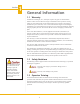
Section 1 General Information 1.1 Warranty LumaSense Technologies, Inc., will repair or replace any parts or material found defective which are due to flaws in design or manufacture when reported in writing within one year from the date of sale (unless another term is agreed to in writing by LumaSense as part of the sale).
Section 1 General Information 1.4 Regulatory Information This section describes how the Infrared camera complies with regulations in certain regions. Any modifications to the Infrared camera not expressly approved by the manufacturer could void the authority to operate the Infrared camera in these regions. USA This Infrared camera generates, uses, and can radiate radio frequency energy and may interfere with radio and television reception.
Section 1 General Information 1.6 Procedure for Factory Repair and Return Do not disassemble any LumaSense instrument unless authorized by the factory. Unauthorized disassembly will void your warranty. If the instrument malfunctions, notify your local LumaSense representative (or call 1-408-727-1600 or fax 1-408-727-1677). If necessary, they will authorize the return of your instrument. Pack the instrument in its original packing, or a carton with sufficient padding to prevent further damage.
To ensure consistent document formatting, this page was intentionally left blank.
Section 2 Introduction The MCS640 represents another milestone in innovative infrared thermal imaging. Designed with advanced maintenance-free electronics and industrial protective packing, the MCS640 offers unparalleled accuracy for demanding industrial and scientific applications. With an unmatched array of protective accessories, the MCS640 demonstrates LumaSense’s commitment to long-term trouble-free operation of these instruments.
Section 2 Introduction 2.2 Environmental Conditions The MCS640 has an internal temperature sensor in the detector and is designed to withstand ambient temperatures from 0°C to 50°C without a temperature-controlled enclosure. The temperature reading can be displayed and read by image processing software via the Gigabit Ethernet connection. In addition to temperature requirements, other environmental factors must also be considered when installing the MCS640 thermal imaging system.
Section 3 Getting Started The MCS640 camera is configured to operate under certain conditions according to user-defined specifications. As such, the camera is assembled, calibrated, and tested at the LumaSense Factory and is delivered with the necessary components to create a fullyoperational system. Assemble the system by connecting the cables as shown on the System Configuration and Wiring drawing supplied with the system. 3.
Section 3 Getting Started 3.1.2 Connecting the Camera to a Network Device Connecting the MCS640 to a Computer using a Straight Cable 1. Connect one end of an RJ45 (Ethernet) cable to the Ethernet port on the camera and the other end to the switch. 2. Connect one end of an RJ45 (Ethernet) cable to your computer and the other end to the switch. 3. The MCS640 requires a Gigabit Ethernet network adapter (see the software manual for a list of supported adapters). All cabling should be Cat5e or Cat 6. 4.
Section 3 Getting Started 3.3 Starting the Software The installation program places your MikroSpec R/T software icon inside of a folder on your hard drive. This program can be accessed through the Windows™ Operating System Start menu. When the system is Online, the software continuously displays the incoming image from the MCS640 and displays user-created Regions Of Interest (ROIs) data on the screen.
To ensure consistent document formatting, this page was intentionally left blank.
Section 4 Principle of Thermal Imaging All materials above 0 degrees Kelvin (-273 degrees C) emit infrared energy. The infrared energy emitted from the measured object is converted into an electrical signal by the imaging sensor (microbolometer) in the camera and displayed on a monitor as a color or monochrome thermal image. The basic principle is explained in the following sections. 4.
Section 4 Principles of Thermal Imaging 4.2 Emissivity Infrared radiation is energy radiated by the motion of atoms and molecules on the surface of object, where the temperature of the object is more than absolute zero. The intensity of the emittance is a function of the temperature of the material. In other words, the higher the temperature, the greater the intensity of infrared energy that is emitted.
Section 4 Principles of Thermal Imaging 4.3 Note: A blackbody is a theoretical surface, which absorbs and re-radiates all the IR energy it receives. It does not reflect or transmit any IR energy. Perfect blackbody surfaces do not exist in nature. Blackbody Radiation The emissivity of a body is defined formally by the equation below as the ratio of the radiant energy emitted by the body to the radiation, which would be emitted by a blackbody at the same temperature.
Section 4 Principles of Thermal Imaging Where in (1) to (3), In radiation of a normal object, as the emissivity is (<1) times of the blackbody, multiply above equation by the emissivity. The following figures show the spectral radiant emittance of a blackbody. (a) is shown by logarithmic scale and (b) is shown by linear scale. Spectral radiant emittance of a blackbody The graphs show that wavelength and spectral radiant emittance vary with the temperature.
Section 4 Principles of Thermal Imaging Absorptivity equals emissivity, thus emissivity can be described by reflectivity and transmissivity. a+t+r=1 In order to obtain the true temperature of an object, it is necessary to obtain the emissivity correctly. Therefore, the emissivity of the object has to be measured by using a blackbody-type source which is closest to an ideal blackbody as possible.
Section 4 Principles of Thermal Imaging Therefore, in order to perform correct measurement for true temperature, the emissivity is determined as follows: 1. By means of a printed table Various books and literature carry physical constants tables, but if the measuring condition is not identical, the constants may not usable. In such cases the literature should be used only for reference. 2.
Section 4 Principles of Thermal Imaging 4.6 Note: For low temperatures, masking tape or cornstarch can be used. Background Noise When measuring the temperature of an object by a radiation thermometer, it is important to take into consideration the above-mentioned emissivity correction as well as the environmental conditions where the measurements will be performed. Infrared rays enter the thermal imager from the measuring object as well as all other objects nearby.
Section 4 Principles of Thermal Imaging 3. Indirect measurement Measure a sample similar to the measured object, and place it in a condition able to be heated by a heater, etc. Then measure the object and the sample alternately with the camera and when the indicated values are identical, measure the sample with a contact-type thermometer. Adjust the emissivity of the thermal imager to cause the temperature readout to match that of the contact measurement. The resulting emissivity is that of the sample. 4.
Section 4 4.8 Principles of Thermal Imaging Emissivity of Various Materials From “Infrared Radiation, a Handbook for Applications” by Mikael A.
Section 4 Principles of Thermal Imaging 20
Section 4 Principles of Thermal Imaging 21
Section 4 Principles of Thermal Imaging 22