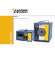
MANUAL M360 Blackbody Calibration Source
Confidential Information The material contained herein consists of information that is the property of LumaSense Technologies and intended solely for use by the purchaser of the equipment described in this manual. All specifications are subject to change without notice. Changes are made periodically to the information in this publication, and these changes will be incorporated in new editions.
Contents 1 General Information...................................................................................................... 5 1.1 Information about the user manual..................................................................... 5 1.1.1 Legend ................................................................................................................. 5 1.2 Safety ..................................................................................................................... 5 1.2.
To ensure consistent document formatting, this page was intentionally left blank.
1 General Information 1.1 Information about the user manual Congratulations on choosing the high quality and highly efficient Mikron blackbody. This manual provides important information about the instrument and can be used as a work of reference for installing, operating, and maintaining your blackbody. It is important that you carefully read the information contained in this manual and follow all safety procedures before you install or operate the instrument.
1.3 Limit of Liability and Warranty All general information and notes for handling, maintaining, and cleaning this instrument are offered according to the best of our knowledge and experience. All Mikron blackbodies from LumaSense Technologies have a regionally effective warranty period. Please check our website at http://info.LumaSenseinc.com/warranty for up-to-date warranty information.
Email: eusupport@LumaSenseinc.com 1.6 Shipments to LumaSense for Repair All RMA shipments of LumaSense Technologies instruments are to be prepaid and insured by LumaSense assigned shipper. For overseas customers, ship units air-freight, priority one. The instrument must be shipped in the original packing container or its equivalent. LumaSense Technologies is not responsible for freight damage to instruments that are improperly packed.
To ensure consistent document formatting, this page was intentionally left blank.
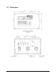
2 Introduction 2.1 Description The M360 blackbody calibration source uniquely combines portability with wide temperature range (50° to 1100 °C), high emissivity and remarkable resolution. An optional precision machined aperture wheel assembly allows different sizes of aperture diameter for applications requiring specific radiating aperture or for verifying field of view of radiometers or infrared thermometers.
2.
M360 Manual Introduction 11
To ensure consistent document formatting, this page was intentionally left blank.
3 Installation & Operation 3.1 Installation Install the blackbody emitter in the desired location that preferably has no moving air near the emitter aperture. The M360 has been factory wired to operate from your standard 100 to 120VAC (230VAC optional) at 10 (5) amps and requires approximately 1000 watts upon power up. Optional voltages are available upon order. Check the specification label in the rear prior to applying power. 3.2 Operation 3.2.1 Starting Up 1.
Blackbody Temperature Blackbody Setpoint 3.2.3 Other Controller Modes If for some reason the power must be turned off while monitoring temperature, you may manually set the power to none by pressing the AUTO, then raise or lower the power level in the same manner used to change the setpoint. Set to 0% to apply NO power to the blackbody. DANGER! NEVER SET POWER TO ANY LEVEL EXCEPT 0% MANUALLY. IF LEFT UNATTENDED, THE BLACKBODY WILL OVERHEAT AND BE DAMAGED.
RS232 interface RS485 interface (2 wire) The controller has a distinct address. The factory address setting is 1. To change the address for RS-232: 1. Press and hold PAGE button. The word ACCESS and Level 1 appear in lower display. 2. Press the UP button until LEVEL 3 appears. 3. Enter PASSCODE by pressing the UP button until 3 appears. Then wait until PASS appears. 4. Press the PAGE button repeatedly until COMMS H appears. 5. Press the SCROLL button until ADDRESS appears. 6.
Each M360 address must be set to a different value. To alter the address if RS485 was ordered: 1. 2. 3. 4. 5. 6. 7. 8. 9. Press and hold PAGE button. ACCESS and Level 1 appear in lower display. Press UP button until LEVEL 3 appears in lower display. Press UP button until 3 appears and wait. Press PAGE until COMMS H appears. Press UP until COMMS J appears. (J COMMS is the RS-485 output) Press SCROLL until ADDRESS appears. Press UP or DOWN to set new address and wait. Press PAGE until ACCESS appears.
Typical Radiance temperature calibration look-up table (LUT) used for model M360 To gain access to the custom look-up table, refer to the 4 square buttons on the face of the controller and use this procedure. 1 2 3 4 1. Press and hold 1 until ACCESS appears. If Access Level and Level 1 appears, skip to step 3. 2. Press 4 until Level 3 appears. 3. Press 4 until 3 appears. Wait until PASS appears. 4. Press 1 until Lin16 appears. 5.
Example: In place of Silver freezing point correction at 961.78 C, you prefer to use 1000C. 1. Using the above steps, set INPUT 9 equal to 1000.0. Set OUTPUT 9 equal to 1000.0. 2. Allow blackbody to control and stabilize at 1000.0C. 3. With your radiance standard, you measure 1001.2 C. 4. Use the above procedure to dial in 1001.2 in the OUTPUT 9 location. 5. Wait for blackbody to re-stabilize at 1000.0 and verify radiance temperature.
Index A Appropriate use 9 D Dimensions 10 Disposal 7 G S Safety 5 Serial Communications 14 Service Request 6 Setpoint 13 Shutting Down 14 Starting Up 13 Storage 7 Support 6 General Information 5 T L Legend 5 Liability 6 Location 13 P Packing 7 Push buttons 13 R Technical Data 9 Transport 7 U Unpacking the Instrument 6 W Warnings 5 Warranty 6 Repair 6, 7 M360 Manual Index 19
To ensure consistent document formatting, this page was intentionally left blank.
Appendix A: CE Certification M360 Manual Appendix A: CE Certification 21