MANUAL M330 Blackbody Calibration Source
Confidential Information The material contained herein consists of information that is the property of LumaSense Technologies and intended solely for use by the purchaser of the equipment described in this manual. All specifications are subject to change without notice. Changes are made periodically to the information in this publication, and these changes will be incorporated in new editions.
Contents 1 General Information...................................................................................................... 5 1.1 Information about the user manual..................................................................... 5 1.1.1 Legend ................................................................................................................. 5 1.2 Safety ..................................................................................................................... 5 1.2.
6.3.2 Secondary Thermocouple Replacement Procedure........................................... 27 6.4 Heater Element Replacement ............................................................................. 27 6.5 Outer Tube Replacement ..................................................................................... 32 6.6 Field Modification for Low Heat Rate ................................................................ 34 6.6.1 I-max Setting ..........................................................
1 General Information 1.1 Information about the user manual Congratulations on choosing the high quality and highly efficient Mikron blackbody. This manual provides important information about the instrument and can be used as a work of reference for installing, operating, and maintaining your blackbody. It is important that you carefully read the information contained in this manual and follow all safety procedures before you install or operate the instrument.
Do not attempt to operate with any of the safety features bypassed or disconnected. Do not place this unit where it will be subject to excessive shock, vibration, dirt, moisture, oil, or other liquids. DANGER! Power is present even if the front panel circuit breaker is in the OFF (0) position! 1.3 Limit of Liability and Warranty All general information and notes for handling, maintaining, and cleaning this instrument are offered according to the best of our knowledge and experience.
Santa Clara, California Telephone: +1 408 727 1600 or +1 800 631 0176 Email: support@LumaSenseinc.com Frankfurt, Germany Telephone: +49 (0) 69 97373 0 Email: eusupport@LumaSenseinc.com Erstein, France Telephone +33 (0)3 88 98 98 01 Email: eusupport@LumaSenseinc.com 1.6 Shipments to LumaSense for Repair All RMA shipments of LumaSense Technologies instruments are to be prepaid and insured by LumaSense assigned shipper. For overseas customers, ship units air-freight, priority one.
To ensure consistent document formatting, this page was intentionally left blank.
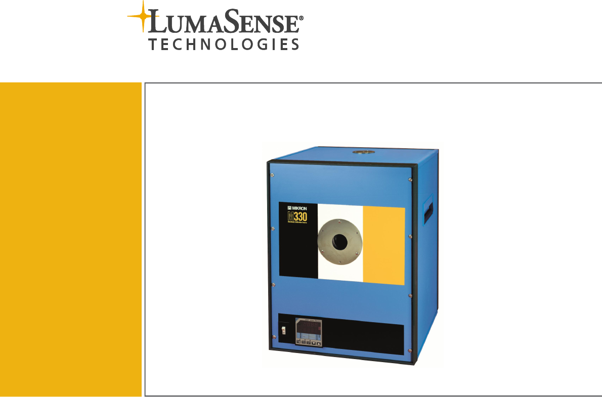
2 Introduction 2.1 Description The M330 is a blackbody calibration source utilizing a digital indicating temperature controller that may be set to any temperature between 300 °C (572 °F) and 1700 °C (3092 °F). A precision thermocouple is embedded in the blackbody cavity providing high accuracy and repeatability. The temperature controller uses the industry standard PID algorithms to control the emitter temperature to within +/-0.5 °C. The blackbody uses a resistive heater that provide long life.
2.
M330 Back Panel M330 Manual Introduction 11
To ensure consistent document formatting, this page was intentionally left blank.
3 Installation Install the blackbody emitter in the desired location that preferably has no moving air near the emitter aperture. The M330 has been factory wired to operate from [ ]208VAC [ ]220VAC [ ]230VAC [ ]240VAC, 20 ampere supply line as per your order. 3.1 Cavity Installation The M330 is designed to allow emitting cavity repair and replacement without sending the entire blackbody to the factory. This M330 was shipped with the cavity NOT installed. Installation is required to operate the M330.
5. As the cavity flange approaches the furnace tube, very gently continue insertion until the cavity stops moving. It is now touching the control thermocouple, so do not force more movement. 6. Final spacing between the cavity collar and the furnace tube should be about 1/8” (3 mm). 3 mm 7. Replace the front panel being careful not to allow it to strike the cavity collar or cavity assembly. Note: Some cracking on the cavity collar is normal. If the M330 is to be moved, remove cavity prior to moving.
4 Operation 4.1 Starting Up 1. Allow the M330 to warm-up to room temperature for at least two hours after unpacking and prior to applying power to remove any condensation. 2. Connect the power cable to a VAC service that matches the power requirement specification noted in the Technical Data section and on the Specification Label located on the rear of the M330. 3. Turn on the power switch/breaker and allow 20 seconds for the system to self test.
4.2 Changing the Setpoint Press either the UP/DWN buttons on the controller. Each press will advance the setpoint 1 degree. To advance faster, press and hold for 5 seconds until it advances a few degrees/second. Let go when it is near the desired setpoint. Press again to bring it to the exact value desired. Note that this setpoint will be retained when power is turned off. Blackbody Temperature Blackbody Setpoint Eurotherm controller 4.2.
4.4 Changing Temperature Units You can select one of three temperature units: Celsius, Fahrenheit, and Kelvin. To change temperature units: 1. Press the PAGE button until ACCESS appears in the lower display. 2. Press the SCROLL button. LEVEL 1 will appear in the lower display. 3. Press the UP button until CONFIG appears in lower display. 4. Press the UP button until 4 appears and wait. 5. Press PAGE until INSTRUMENT appears. 6. Press the UP button until Units Page appears. 7. Press the SCROLL button.
4.5.2 RS485 Option RS485 two wire is available as an option. The connection scheme is shown below: M330 Unit 1 (Address 1) M330 Unit 2 (Address 2) RS485 for multi-drop applications Each M330 address must be set to a different value. To change the address of an M330: 1. Press the PAGE button. ACCESS appears in the lower display. 2. Press the SCROLL button. LEVEL 1 appears in the lower display. 3. Press the UP button until LEVEL 3 appears in the lower display. 4.
4.6 PID Tuning Constants The PID tuning constants have been factory set for optimum performance and are noted below.
To ensure consistent document formatting, this page was intentionally left blank.
5 Maintenance 5.1 Cavity Life The life expectancy of the cavity depends on the time and temperature of operation. The higher the temperature, the shorter the life span. At temperatures near the upper end of the range, the life expectancy is shortened by approximately 50%. We recommend an occasional visual check be made to insure maximum system integrity. The cavity is field replaceable without disturbing any control thermocouples. Refer to Section 3.1 Cavity Installation. 5.
To ensure consistent document formatting, this page was intentionally left blank.
6 Service 6.1 Controller Calibration (Adjustment) The M330 has a precision, thermocouple monitoring the emitter temperature. The THERMOCOUPLE measurements are passed through a look-up table that ultimately provides the correct exit radiance temperature for the indicated temperature. A separate calibration report is included. This controller has been programmed to contain a custom look-up table that may be used to precisely calibrate the controller/indicator against reference THERMOCOUPLE’s.
2. 3. 4. 5. 6. 7. 8. 9. 10. 11. 12. 13. Press 2. Press 4 until Level 3 appears. Press 4 until 3 appears. Wait. Press 1 until INPUT OPERS and Cust Lin 1 Page appears. Press 2 until display shows the Output # that corresponds to the calibration point shown in the listing on the previous page. Use the UP/DWN buttons (3 and 4) to dial in the measured radiance temperature from a freezing point transfer device or other radiance standard. Press 2 to view/change more correction points.
0 - 510 °C 510 - 710 °C 710 - 1380 °C 1380 - 1750 °C(end) 6.3 PID1 PID2 PID3 PID4 (PB1, Int1, Rate1) (PB2, Int2, Rate2) (PB3, Int3, Rate3) (PB4, Int4, Rate4) Thermocouple Replacements The M330 has two thermocouples; the primary that senses the cavity temperature and the secondary that measures air temperature inside the heater chamber. The secondary thermocouple is only used for monitoring the chamber for heat rate control and safety over temperature shut-down.
6.3.1 Primary Thermocouple Replacement Procedure 1. Remove the screws holding the M330 front and rear panels. 2. Lower the front and rear panels, as shown in photos. 3. Disconnect heater supply wires. 4. Loosen and remove four shelf mounting screws. 6 Primary Thermocouple 4 4 5 Front panel 5. Slide shelf out of enclosure enough to get access to the primary thermocouple. 6. Loosen thermocouple clamp screws but do not remove screws entirely. Measure and mark existing thermocouple depth.
Warning: Electrical Shock Hazard! This equipment is to be serviced by trained personnel only. 8. Replace with new thermocouple at same depth as old thermocouple. 9. Wrap the thermocouple with ceramic wrapping at the clamp in the same manner as removed. 9 10. Replace cavity assembly into M330 in reverse order. 11. Install the replaceable cavity according to Chapter 3 M330 Cavity Installation. 12. Check calibation and adjust according to Section 5.6 Controller Calibration. 6.3.
1 to 10 ohms OK 1 to 10 ohms OK 1 to 10 ohms OK 1 to 10 ohms OK To check which heating element is broken: 1. Disconnect the AC power. 2. Locate which heating element is broken. Disconnect only one of the wires attached to an end strap. 3. Use Ohmmeter to measure across each heating element. If any of the above readings are OPEN circuit or greater than 100 ohms, then the element is bad and needs replacement. Note: Sometimes the element may show OK when it is cold, but opens when it gets hot.
To replace a heating element: To replace a heater, both thermocouples must be moved out of the way of the heaters. Then the top cover must be removed. Follow the steps below. 1. 2. 3. 4. Disconnect all strap clamps from each heater. Remove straps and put aside. Loosen both thermocouple clamps. Pull each thermocouple at least ½ of the way out of the chamber. Remove screws holding top cover. 1 2 Loosen t/c clamps.
5. Pull top cover with heaters AND the three insulation blocks up and out. 6. Remove only the bad heating element by loosening the ceramic clamp for that heater. No need to remove any other ceramic clamps. 6 7 7. Pull out the bad heating element and replace with the new one. 8. Replace ceramic clamp at top cover. Do not over tighten. 9. Replace top cover with all insulation boards.
10. Replace straps. 11. Replace main supply wires to end straps. Proper connection of electrical straps and clamps. Top view.
6.5 Outer Tube Replacement Warning: Electrical Shock Hazard! This equipment is to be serviced by trained personnel only. 1. Loosen clamp to allow tube to slide out. 1 Side view Front view 2. Loosen clamp screws to remove thermocouple. 3. Remove thermocouple.
4. Remove (chip away) ceramic cement at this location with small hammer and screwdriver. On older models, ceramic cement must be broken (chipped away) to allow tube to slide out. 5. Slide outer tube out of cavity. Remove top cover screws only if the tube cannot be easily removed. 6 5 6. Save the plug for use in the new tube. 7. Replace with new tube. 8. Install thermocouple. 9. Clamp new tube in place.
6.6 Field Modification for Low Heat Rate Warning: Electrical Shock Hazard! This equipment is to be serviced by trained personnel only. This procedure is to remedy a problem if the over-temperature cut-off switch causes the M330 to disconnect heater power before reaching 1700 °C. Newer models have the cut-off switch in the “new location” and this procedure does not apply. 1. Remove the M330 Rear Panel. 2. Relocate the Over Temperature Manual Reset Thermostat as shown below.
Top view of new Thermostat location. Rear of blackbody Front of blackbody 3. Move Transformer Primary tap from 230 VAC (H3) to 208 VAC (H2) as shown below if operating on 220 VAC (only). Power now goes between H1 and H2 as shown below. Do not change H3 to H2 if operating at 230 VAC.
Warning: Electrical Shock Hazard! This equipment is to be serviced by trained personnel only. 4. Program M330 Controller according to the procedure below. To gain access to the custom program, refer to the 4 square buttons on the face of the controller and use this procedure. 1 1. 2. 3. 4. 5. 6. 7. 8. 9. 10. 11. 12. 13. 14. 15. 16. 17. 18. 19. 20. 21. 22. 2 3 4 Press 1 until ACCESS appears. Press 2. Press 4 until Level 3 appears. Press 4 until 3 appears. Wait.
1. Remove rear cover. 2. Attach a Clamp-On Ammeter to one of the supply wires. This meter should measure True RMS current. Typical measurement will be between 0 and 15A. See photo below. Clamp-on Anmeter (True RMS) 3. Allow the M330 to run until at least 800 °C. At this time, you should see the controller output power demand = 100%. 4. At this time, adjust the I-max setting on SCR as shown in next picture. This should be adjusted to obtain between 14 and 15 Amps when the controller demands 100%.
To ensure consistent document formatting, this page was intentionally left blank.
Index A Appropriate use 9 B Baud Rate 17 C Cavity life 21 Cleaning 21 Controller Adjustment 23 Controller Calibration 23 O Operation 15 Outer Tube 32 Outer Tube Replacement 32 P Packing 7 Parity 17 PID Tuning Constants 19 Push buttons 15 R D Repair 6, 7 Dimensions 10 Disposal 7 S Heater Element 27 Safety 5 Safety Interlocks 21 Serial Communications 17 Service 23 Service Request 6 Setpoint 16 Shutting Down 16 Spectral Correction 41 Starting Up 15 Storage 7 Support 6 I T I-max 36 Inspections 21
To ensure consistent document formatting, this page was intentionally left blank.
Appendix A: M330 Spectral Correction Procedure 1. Set the M330 controller to the desired radiance temperature referenced to the 1um standard. 2. Locate the Spectral Band Column that matches your pyrometer. 3. Look up the corresponding expected radiance temperature output for the selected spectral band. 4. Adjust the pyrometer under calibration to the new radiance temperature just found in step 3. Example: Desired temperature is 1000 °C. Your pyrometer is spectral band E.
950 948.1 943.2 940.9 937.3 933.9 935.4 935.7 942.1 966.8 975 973.1 967.9 965.6 961.8 958.3 959.9 960.2 1000 998.0 992.7 990.2 986.3 982.7 984.5 984.8 991.6 1025 1022.9 1017.4 1014.9 1010.9 1007.1 1009.0 1009.3 1016.4 1050 1047.8 1042.1 1039.5 1035.4 1031.5 1033.5 1033.8 1041.1 1075 1072.7 1066.8 1064.2 1059.9 1055.9 1058.0 1058.4 1065.9 1100 1097.7 1091.6 1088.8 1084.4 1080.3 1082.5 1082.9 1090.6 1125 1122.6 1116.3 1113.4 1108.9 1104.
Appendix B: Optional Blackbody Spectral Radiance Correction Software for M330 Blackbody Source Current blackbody temperature updated one reading/second Type desired blackbody setpoint here. Current spectral response used. Laboratory temperature. (Default is 23C.) SENDs new setpoint to the blackbody. Select Mikron’s Spectral band or enter your own filter’s HPBW points if you select “SPECIAL”.
To ensure consistent document formatting, this page was intentionally left blank.
Appendix C: CE Certification M330 Manual Appendix C: CE Certification 45